
Cathode protection current supplementing device for solar gas pipeline

A gas pipeline and cathodic protection technology, which is applied in the field of circuit protection devices, can solve the problems of easy corrosion of solar gas pipelines, general pipeline stability, and short service life, and achieve improved sealing and moisture resistance effects, improved shock absorption effects, The effect of improving stability

Pending Publication Date: 2021-10-01
华勘工程实业有限公司
View PDF0 Cites 0 Cited by
  • Summary
  • Abstract
  • Description
  • Claims
  • Application Information

AI Technical Summary

Problems solved by technology

[0005] In order to make up for the deficiencies of the existing technology, it solves the problems that the solar gas pipeline is easy to corrode, the service life is short, and the stability effect of the pipeline is general.

Method used


Image

  • Cathode protection current supplementing device for solar gas pipeline
  • Cathode protection current supplementing device for solar gas pipeline
  • Cathode protection current supplementing device for solar gas pipeline

Examples


Embodiment 1

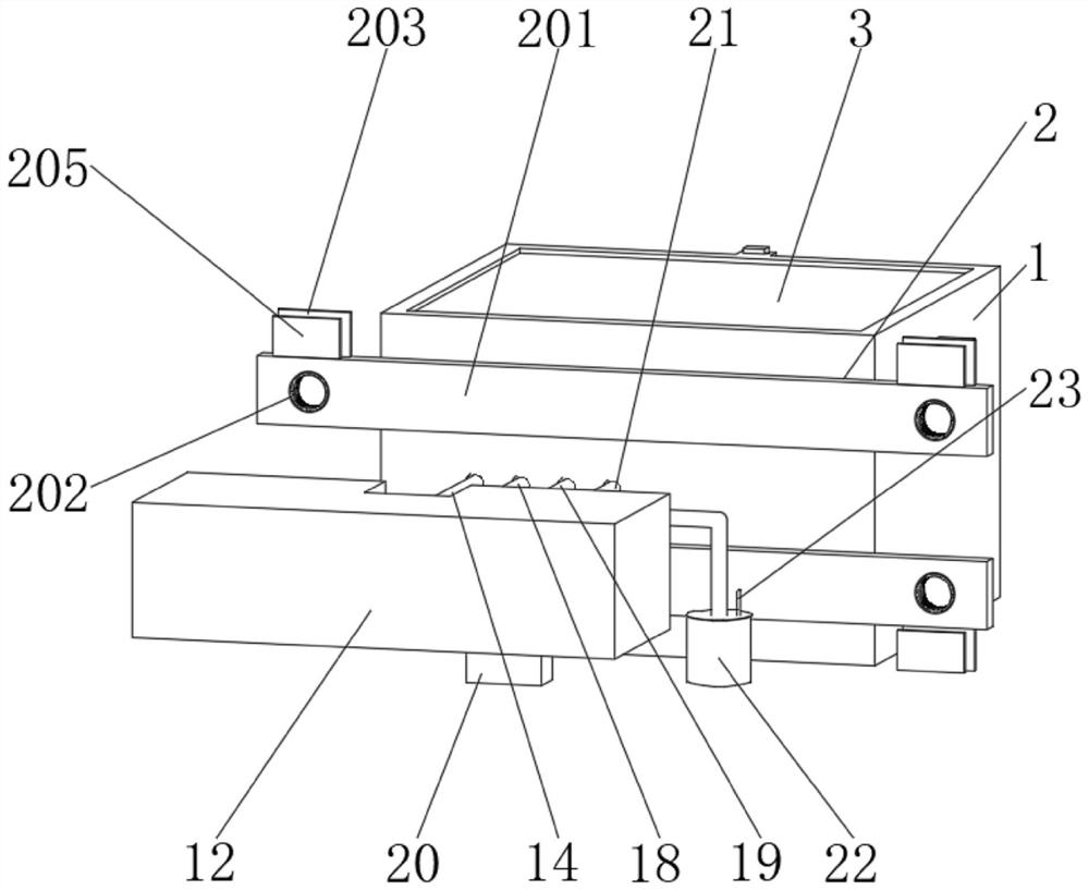
[0029] see figure 1 and image 3 As shown, a solar gas pipeline cathodic protection current supplementary device includes a protective box 1 and a pipeline controller 12, the outer wall of the protective box 1 is provided with a connecting mechanism 2, and the top of the protective box 1 is provided with a top plate 3, and the end of the top plate 3 The first hollow plate 4 is arranged on the top, and the top of the first hollow plate 4 is provided with a second hollow plate 5, and the inside of the second hollow plate 5 is provided with a card plate 6, and the bottom of the protective box 1 is provided with a moisture-proof drawer 7, And the top of the moisture-proof drawer 7 is provided with a partition 8, the top of the moisture-proof drawer 7 is provided with a threaded plate 9, and the inner side of the threaded plate 9 runs through a threaded rod 10, and the end of the threaded rod 10 is reserved with a threaded groove 11.

[0030] The connecting mechanism 2 comprises c...

Embodiment 2

[0035] see figure 2 and Figure 4-6As shown, compared with Example 1, as another embodiment of the present invention, the pipeline controller 12 is arranged outside the protective box 1, and the middle position of the pipeline controller 12 is provided with a power line 13, and the side of the power line 13 The side is connected with the output cathode cable 14, the end of the cathode cable 14 is provided with a potentiostat 15, and the top of the potentiostat 15 is provided with a cooling tube 16, and the end of the cooling tube 16 is equipped with a dust-proof net 17, and the cathode cable 14 The side of the zero position connection female cable 18 is provided, and the side of the zero position connection female cable 18 is provided with an output anode cable 19, and the end of the output anode cable 19 is provided with an auxiliary anode 20, and the side of the output anode cable 19 A reference electrode cable 21 is provided, and a hydrochloric acid solution tube 22 is pr...


PUM


Abstract

The invention belongs to the field of circuit protection devices, and particularly relates to a cathode protection current supplementing device for a solar gas pipeline, which comprises a protection box and a pipeline controller, wherein a connecting mechanism is arranged on the outer wall of the protection box, a top plate is arranged at the top of the protection box, and a first hollowed-out plate is arranged at the end part of the top plate; a second hollowed-out plate is arranged at the top of the first hollowed-out plate, a clamping plate is arranged in the second hollowed-out plate, a damp-proof drawer is arranged at the bottom of the protection box, a partition plate is arranged above the damp-proof drawer, a threaded plate is arranged at the top of the damp-proof drawer, a lead screw penetrates through the inner side of the threaded plate, and a threaded groove is reserved in the end part of the lead screw; the pipeline controller is arranged outside the protection box, a power line is arranged in the middle of the pipeline controller, and the side of the power line is connected with an output cathode cable. The problems that the solar gas pipeline is prone to corrosion, short in service life and common in stability effect are solved.

Description

technical field [0001] The invention relates to the field of circuit protection devices, in particular to a current supplementary device for cathodic protection of solar gas pipelines. Background technique [0002] Cathodic protection current is a kind of electrochemical protection technology. Its principle is to apply an external current to the surface of the corroded metal structure, and the protected structure becomes a cathode, so that the electron migration of metal corrosion is inhibited, and the corrosion is avoided or weakened. Cathodic protection has been developed for many years, and the industry has summed up the current density required by cathodic protection systems in various environments, which can be used as a reference in actual construction in the future. However, the current density recommended in the past was too conservative, resulting in a lot of material energy. Therefore, when carrying out a project, investigate the structure in the local similar envi...

Claims


Application Information

Patent Timeline
Patent Type & Authority Applications(China)
IPC IPC(8): C23F13/06C23F13/22
CPCC23F13/06C23F13/22C23F2213/32
Inventor 王辉王鑫史晓青王银华陈登平任佳林
Owner 华勘工程实业有限公司
Learn More