
Automatic assembly equipment for bottle caps with lifting ropes

A technology for automatic assembly and bottle caps, applied in metal processing equipment, devices for coating liquid on the surface, metal processing, etc., can solve the problems of numerous steps, time-consuming and labor-intensive, inability to effectively improve efficiency, etc., and achieve stable and reliable structure, Improve work efficiency and prevent excessive force

Inactive Publication Date: 2021-10-01
宁波市鄞州承润科技有限公司
View PDF0 Cites 0 Cited by
  • Summary
  • Abstract
  • Description
  • Claims
  • Application Information

AI Technical Summary

Problems solved by technology

In the process of producing rope bottle caps, the staff needs to pick up the outer cap and apply glue to the inner wall of the outer cap, then pick up the inner cap, align the protrusions of the inner cap with the square holes of the outer cap, and then press the inner cap. Into the outer cover, the steps are numerous and time-consuming and labor-intensive, which cannot effectively improve efficiency

Method used


Image

  • Automatic assembly equipment for bottle caps with lifting ropes
  • Automatic assembly equipment for bottle caps with lifting ropes
  • Automatic assembly equipment for bottle caps with lifting ropes

Examples


Embodiment Construction

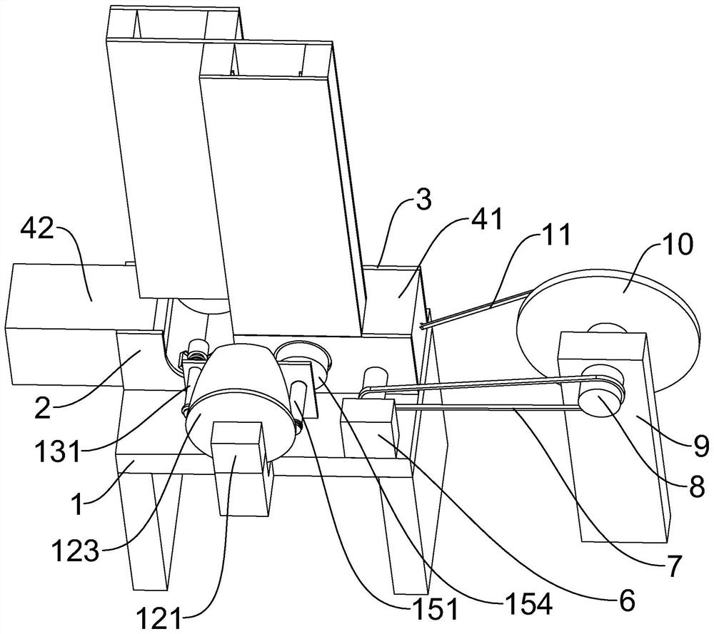
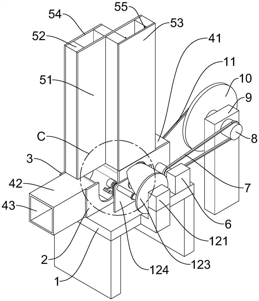
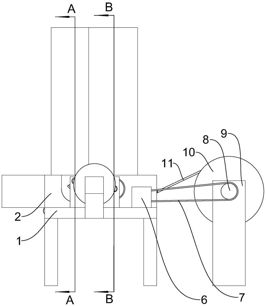
[0038] Such as Figure 1 to Figure 17 As shown, an automatic assembly device for a rope bottle cap includes vertical blocks on the left and right sides, the upper end of the vertical block is provided with a platform 1, and the upper end of the platform 1 is provided with a front baffle 2 and a rear baffle 3 arranged in parallel, The upper end of the front baffle 2 and the rear baffle 3 is provided with a blanking box 5 for blanking the outer cover and the inner cover, and the platform 1, the front baffle 2, the rear baffle 3, and the blanking box 5 are equipped with a conveyor Part 4, the upper end of the conveying part 4 is provided with a U-shaped groove, the upper end of the platform 1 is provided with a first stepping motor 6, the right side of the vertical block on the right is provided with a support block 9, and the upper end of the support block 9 is rotatably provided with The first rotating shaft 8, the first rotating shaft 8, and the output shaft of the first stepp...


PUM


Abstract

The invention discloses automatic assembly equipment for bottle caps with lifting ropes. The equipment comprises vertical blocks at the left side and the right side, wherein a platform is arranged at the upper ends of the vertical blocks; a front baffle and a rear baffle which are arranged in parallel are arranged at the upper end of the platform; a discharging box used for discharging outer caps and inner caps is arranged at the upper ends of the front baffle and the rear baffle; a conveying piece is matched among the platform, the front baffle, the rear baffle and the discharging box in a sliding mode; a U-shaped groove is formed in the upper end of the conveying piece; a first stepping motor is arranged at the upper end of the platform; a supporting block is arranged at the right side of the vertical block at the right side; a first rotating shaft is rotationally arranged at the upper end of the supporting block; and a toothed belt is connected between the first rotating shaft and an output shaft of the first stepping motor. The equipment has the advantages that the structure is stable and reliable, falling of the outer caps into the U-shaped groove, gluing of the inner walls of the outer caps, falling of the inner caps into the U-shaped groove, embedded pressing of the inner caps into the outer caps, falling of the assembled bottle caps and resetting of all parts can be sequentially and automatically completed, glue falling from a glue sleeve can be collected, and the working efficiency is improved.

Description

technical field [0001] The invention relates to an assembly device, in particular to an automatic assembly device for a rope bottle cap. Background technique [0002] The rope bottle cap refers to a glass bottle cap with a rope for carrying the glass bottle. In the process of producing rope bottle caps, the staff needs to pick up the outer cap and apply glue to the inner wall of the outer cap, then pick up the inner cap, align the protrusions of the inner cap with the square holes of the outer cap, and then press the inner cap. Into the outer cover, the steps are numerous and time-consuming and laborious, and the efficiency cannot be effectively improved. Contents of the invention [0003] The main purpose of the present invention is to provide an automatic assembly equipment for rope bottle caps, which has a stable and reliable structure, can automatically lower the material into the U-shaped groove, and press the inner cap into the outer cap after the outer cap is coate...

Claims


Application Information

Patent Timeline
Patent Type & Authority Applications(China)
IPC IPC(8): B23P19/04B23P19/00B05C7/06B05C11/10
CPCB23P19/04B23P19/001B05C7/06B05C11/10
Inventor 不公告发明人
Owner 宁波市鄞州承润科技有限公司
Learn More