A kind of CNC bending equipment for metal product production
A technology for metal products and equipment, which is applied in the field of CNC bending equipment for metal product production, can solve problems such as low bending efficiency, achieve the effects of improving bending efficiency, improving bending stability, and improving practicability
- Summary
- Abstract
- Description
- Claims
- Application Information
AI Technical Summary
Problems solved by technology
Method used
Image


Examples
Embodiment 1
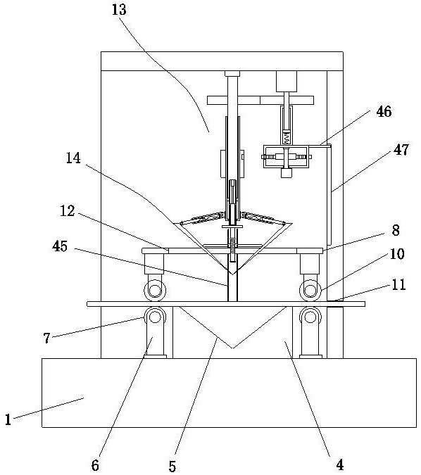
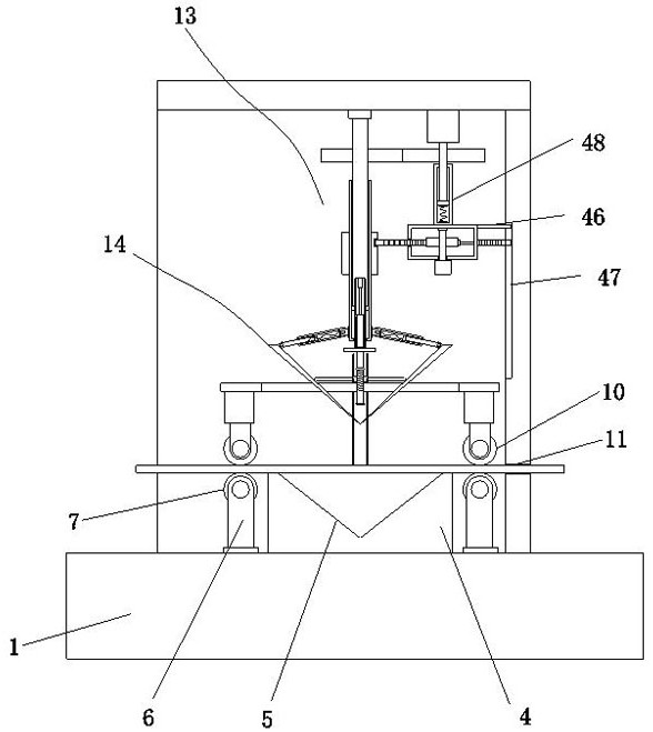
[0035] Embodiment one, by Figure 1 to Figure 8 Given, the present invention comprises operating table 1, and the top of operating table 1 is provided with support frame 2, and one side of support frame 2 is provided with the mounting plate 3 that is connected with operating table 1, is provided with through hole 11 on the mounting plate 3, operates The top of the table 1 is provided with a bending seat 4 located on one side of the support frame 2 and the mounting plate 3, and the middle position of the top of the bending seat 4 is provided with a bending groove 5, and the two sides of the bending seat 4 are symmetrically provided with a The support seat 6 connected to the top of the table 1 is connected with the support roller 7 on the support seat 6, the support plate 8 connected with the side wall of the support frame 2 is arranged above the support roller 7, and the middle position of the support plate 8 is provided with a slot 12. Both sides of the bottom end of the suppo...
Embodiment 2
[0040] Embodiment two, on the basis of embodiment one, by figure 1 , figure 2 and image 3 Given, the pressing group includes an electric telescopic rod 9 and a pressing roller 10, the bottom end of the support plate 8 is symmetrically provided with an electric telescopic rod 9, and the bottom end of the electric telescopic rod 9 is rotatably connected with a pressing roller 10 located at the top of the supporting roller 7, The worker puts the metal to be processed on the top of the two support rollers 7, and makes one end of the metal plate go through the inside of the through hole 11, and starts the electric telescopic rod 9, so that the electric telescopic rod 9 drives the pressing roller 10 to move down, and The pressing roller 10 is pressed on the top of the metal product to realize the clamping of the metal product by the supporting roller 7 and the pressing roller 10, which improves the stability of the bending process of the metal product and further improves the ben...
Embodiment 3
[0041] Embodiment three, on the basis of embodiment one, by figure 1 , figure 2 , image 3 , Figure 5 and Figure 6 Given, the connecting group one includes base one 26, rotating seat 27, connecting cylinder 28, movable pull rod 29 and base two 30, and the mounting ring 23 is installed on the outer bottom end of the internally threaded cylinder 20, and the two sides of the mounting ring 23 are symmetrical There is a base one 26, on which the base one 26 is rotatably connected with a rotating base 27, one end of the rotating base 27 is connected with the connecting cylinder 28, and the inside of the connecting cylinder 28 is elastically connected with a movable pull rod 29, a bending plate 24 and a bending plate. A base 2 30 is provided on the top of one side of the plate 25, and the base 2 30 is rotationally connected with the movable pull rod 29;
[0042] When the bending plate one 24 and the bending plate two 25 are deflected at an angle, the movable pull rod 29 will b...
PUM
 Abstract
Description
Claims
Application Information
 - R&D
- Intellectual Property
- Life Sciences
- Materials
- Tech Scout
- Unparalleled Data Quality
- Higher Quality Content
- 60% Fewer Hallucinations
Browse by: Latest US Patents, China's latest patents, Technical Efficacy Thesaurus, Application Domain, Technology Topic, Popular Technical Reports.
© 2025 PatSnap. All rights reserved.Legal|Privacy policy|Modern Slavery Act Transparency Statement|Sitemap|About US| Contact US: help@patsnap.com