Eureka AIR delivers breakthrough ideas for toughest innovation challenges, trusted by R&D personnel around the world.

Wastewater solid-liquid separator for chemistry and chemical engineering

A solid-liquid separator, chemical technology, applied in the direction of liquid separation, filtration separation, separation methods, etc., can solve the problems of unable to clean the sediment, unable to clean the filter, etc.

Active Publication Date: 2021-10-01
海南哈勃新能源技术合伙企业(有限合伙)
View PDF15 Cites 3 Cited by
  • Summary
  • Abstract
  • Description
  • Claims
  • Application Information

AI Technical Summary

Problems solved by technology

[0004] The object of the present invention is to provide a chemical and chemical wastewater solid-liquid separator capable of solid-liquid separation of chemical and chemical wastewater, and capable of cleaning up accumulated sediment, so as to overcome the inability of the above-mentioned existing devices to remove the sediment accumulated in the tank. Defects such as cleaning of objects and not being able to clean the filter screen

Method used


Image

  • Wastewater solid-liquid separator for chemistry and chemical engineering
  • Wastewater solid-liquid separator for chemistry and chemical engineering
  • Wastewater solid-liquid separator for chemistry and chemical engineering

Examples


Embodiment 1

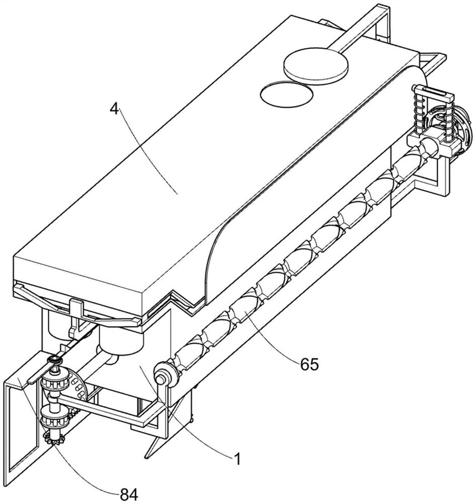
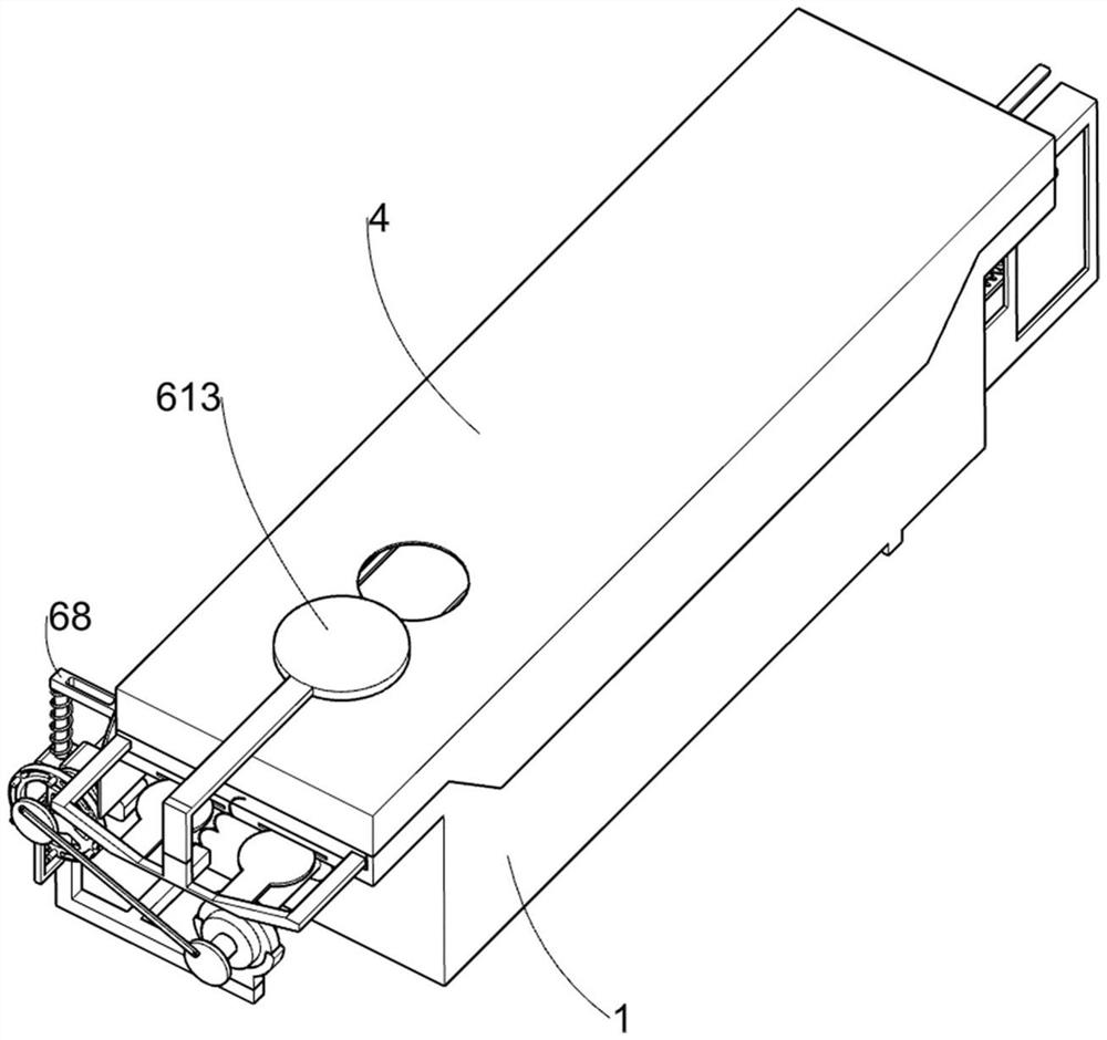
[0031] A kind of waste water solid-liquid separator for chemical industry, such as Figure 1-10 As shown, it includes a waste water collection box 1, a filter box 2, a slide rail plate 3, a sealing cover 4, a rotary stirring mechanism 5, a reciprocating oil scraping and water injection mechanism 6, a rotary push-out mechanism 7 and a toggle mechanism 8 for collecting sewage. A filter box 2 for filtering sediment is fixedly installed at the bottom of the waste water collection box 1, a slide rail plate 3 is positioned on the top surface of the waste water collection box 1, and a seal for sealing the waste water collection box 1 is fixedly installed on the top surface of the slide rail plate 3. The cover 4 and the rotating stirring mechanism 5 are set on the waste water collection tank 1, and the reciprocating oil scraping and water injection mechanism 6 for scraping off the oil stain on the surface of the sewage is arranged on the rotating stirring mechanism 5, and the reciproca...

Embodiment 2

[0041] On the basis of Example 1, such as Figure 11-12 As shown, it also includes a scraping mechanism 9, the scraping mechanism 9 is arranged on the filter box 2, and the scraping mechanism 9 is used to scrape off the sediment remaining inside the special-shaped push plate 75, and the scraping mechanism 9 includes a limit slide bar 91, the second extension spring 92, the second rotating shaft 93, the triangular block 94, the first torsion spring 95, the L-shaped scraper 96, the belt shaft scraper 97 and the second torsion spring 98, the limit slide bar 91 can be lifted connected to the filter box 2 in the same way, the filter box 2 is fixedly connected with a second tension spring 92, and one end of the second tension spring 92 away from the filter box 2 is fixedly connected with the limit slide bar 91, and the limit slide bar 91 The rotation type is connected with a second rotating shaft 93, and a triangular block 94 is welded on the second rotating shaft 93. The triangular...


PUM


Abstract

The invention relates to the field of industrial wastewater recovery treatment, in particular to a chemical and chemical wastewater solid-liquid separator, and the separator comprises a wastewater collecting tank, a filter tank, a slide rail plate, a sealing cover, a rotary stirring mechanism and the like. A filter tank is fixedly mounted at the bottom of the wastewater collection tank, a slide rail plate is positioned on the top surface of the wastewater collection tank, a sealing cover is fixedly mounted on the top surface of the slide rail plate, and the rotary stirring mechanism is arranged on the wastewater collection tank. Through cooperation of a swing rod and a fourth reset spring, a special-shaped stirring plate reciprocates left and right, the special-shaped stirring plate intermittently blocks a filtering box, filtered sewage is intermittently discharged from the filtering box, the special-shaped stirring plate and a special-shaped push plate are matched in a staggered mode, sewage in a waste water collecting box is prevented from flowing out, and the solid-liquid separation effect on the sewage is achieved.

Description

technical field [0001] The invention relates to the field of recycling and treatment of industrial waste water, in particular to a solid-liquid separator for chemical and chemical waste water. Background technique [0002] With the rapid development of the domestic economy, my country, as a large industrial country, has a lot of chemical plants. While driving the rapid economic development, the pollution of chemical wastewater to the environment has intensified. Therefore, waste liquid recovery is very important. There are three methods of wastewater treatment. Physical treatment method, chemical treatment method, physical chemical method, wastewater physical treatment method is to recover and separate small dissolved objects and suspended pollutants in wastewater. [0003] During the process of physical wastewater treatment, the chemical properties of the pollutants do not change. After the reaction is completed, sediments will be produced in the wastewater. There are variou...

Claims


Application Information

Patent Timeline
IPC IPC(8): B01D29/03B01D29/92B01D35/16C02F1/40B08B1/00B08B1/02
CPCB01D29/03B01D29/92B01D35/16C02F1/40B08B1/165B08B1/20
Inventor 范春红
Owner 海南哈勃新能源技术合伙企业(有限合伙)
Why Eureka
Eureka Blog
Learn More