


Quick Research
Generate reliable direction feasibility study reports for your R&D in just a few steps.

Technical Q&A
Discover and master advanced knowledge NOW. Basics, ideas, possibilities, all at once.

Find Solutions
As an expert in R&D theories, this can generate solutions to your technical problems instantly.

Evaluate Feasibility
Analyze your overall solution with one click, know your potential R&D risks in advance.

Monitor Landscape
Get weekly tech updates, stay abreast of the latest tech innovations and key insights.
Ring network power supply system fault positioning system and method based on communication injection waveform
A fault location and power supply system technology, applied to electrical components, circuit devices, emergency protection circuit devices, etc., can solve feeder misoperation or refusal to operate, fault location algorithm failure, protection device current amplitude, angle uncertainty, etc. problems, to achieve stable and reliable data, reduce the scope of power outages, and avoid the effects of collection costs
- Summary
- Abstract
- Description
- Claims
- Application Information
AI Technical Summary
Problems solved by technology
Method used
Image

Examples
Embodiment 1
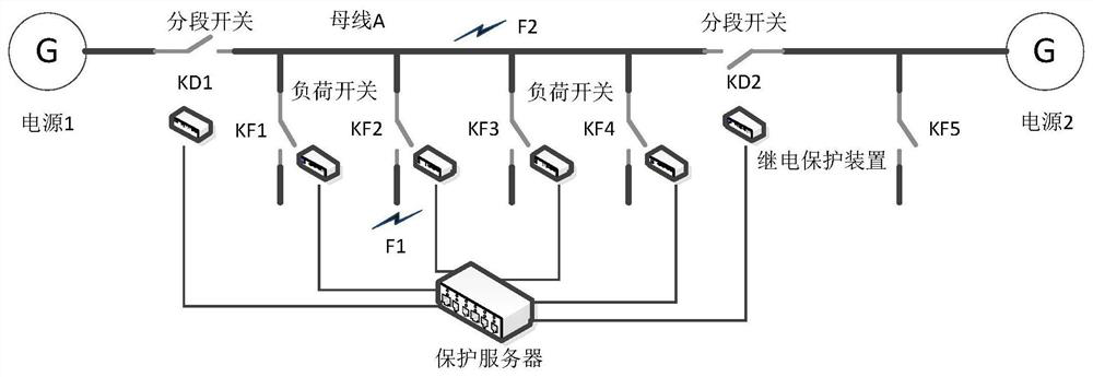
[0026] Embodiment 1: A ring network power supply system fault location system based on communication injection waveforms, the location system is composed of a relay protection device installed at each load / section switch and a protection server communicating with each protection device, The protection server and the relay protection device use optical fiber for full-duplex communication. Each switch is equipped with a relay protection device, and each bus section is equipped with a protection server. The relay protection device of each bus section communicates with the corresponding protection device through the communication interface. The server is connected, and the faults under each switch are removed by the relay protection device of the switch. The protection server realizes the data sharing of all relay protection devices, so that each protection device can use the relay protection data of the entire busbar when making logical judgments. Realize network fault discriminat...
Embodiment 2
[0027] Embodiment 2: A ring network power supply system fault location method based on communication injection waveforms, the method includes the following steps:
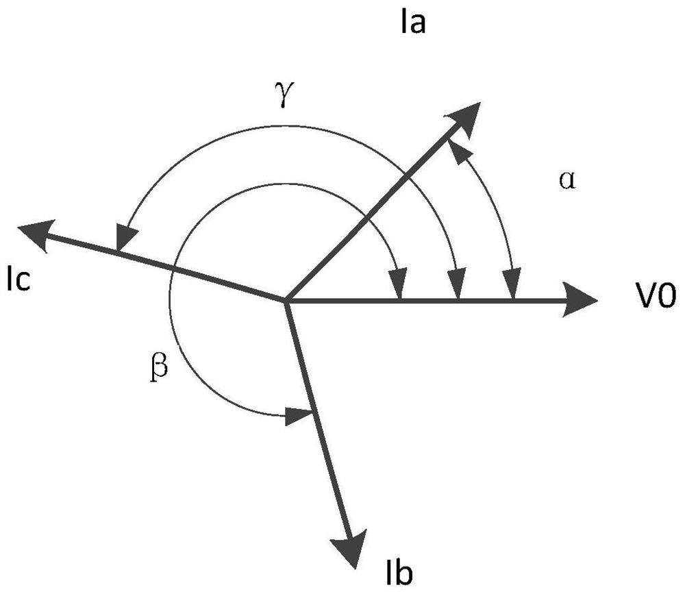
[0028] Definition: The current phase angle refers to the angle difference between the current flowing through the switch and the reference waveform. The sudden change of the phase angle means that the angle change of the current phase angle between this cycle and the previous cycle exceeds 90 degrees. The installation direction of the current transformer of the relay protection device is uniform. , define the load that flows from the power source to the bus in this section as the positive direction.
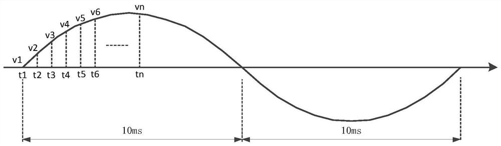
[0029] S1: The relay protection device has a unique ID address in the whole network, and collects the three-phase current at the load / section switch according to the inherent sampling frequency;
[0030] S2: The protection server sends the sampling data of the fixed power frequency waveform according to the sampling f...
PUM
 Abstract
Description
Claims
Application Information
 - R&D Engineer
- R&D Manager
- IP Professional
- Industry Leading Data Capabilities
- Powerful AI technology
- Patent DNA Extraction
Browse by: Latest US Patents, China's latest patents, Technical Efficacy Thesaurus, Application Domain, Technology Topic, Popular Technical Reports.
© 2024 PatSnap. All rights reserved.Legal|Privacy policy|Modern Slavery Act Transparency Statement|Sitemap|About US| Contact US: help@patsnap.com