A ring network power supply system fault location system and method based on communication injection waveform

A fault location and power supply system technology, applied to electrical components, circuit devices, emergency protection circuit devices, etc., can solve fault location algorithm failure, feeder misoperation or refusal to operate, protection device current amplitude, angle uncertainty, etc. problems, to achieve the effect of avoiding collection costs, stable and reliable data, and reducing the scope of power outages

Active Publication Date: 2022-06-17
南京弘毅电气自动化有限公司
View PDF2 Cites 0 Cited by
  • Summary
  • Abstract
  • Description
  • Claims
  • Application Information

AI Technical Summary

Problems solved by technology

[0004] The present invention is aimed at the problems existing in the prior art, and only uses the fault location method of each node fault current in the ring network power supply system to determine the fault location, so as to solve the uncertainty of the current amplitude and angle flowing through the protection device when the fault occurs , causing the original relay protection and feeder automation to malfunction or refuse to operate, the traditional fault location algorithm fails, and the problem of not meeting the reliability requirements of power supply

Method used


Image

  • A ring network power supply system fault location system and method based on communication injection waveform
  • A ring network power supply system fault location system and method based on communication injection waveform
  • A ring network power supply system fault location system and method based on communication injection waveform

Examples


Embodiment 1

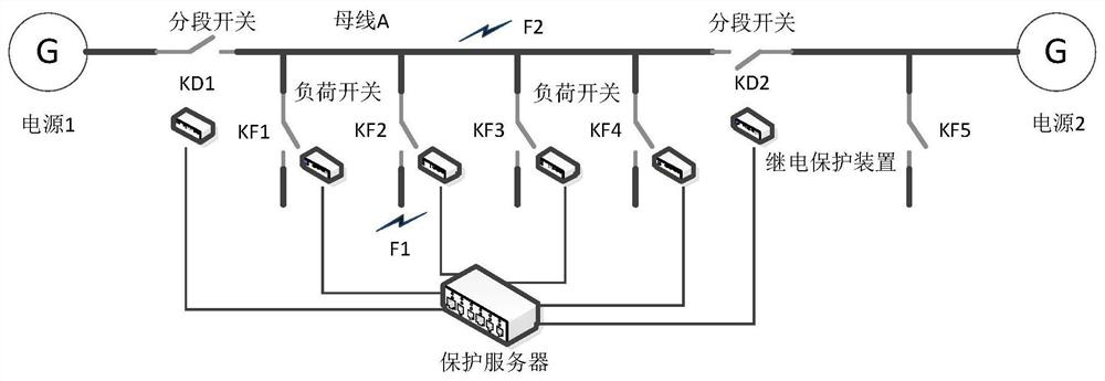
[0026] Embodiment 1: a fault location system for a ring network power supply system based on a communication injection waveform, the location system consists of a relay protection device installed at each load / section switch and a protection server that communicates with each protection device, The protection server and the relay protection device use optical fiber for full-duplex communication. Each switch is equipped with a relay protection device, and each busbar is equipped with a protection server. The relay protection device of each busbar communicates with the corresponding protection device through the communication interface. The relay protection device of the switch is responsible for removing the fault under each switch, and the protection server realizes the data sharing of all relay protection devices, so that each protection device can use the entire busbar relay protection data when making logical judgments. Realize network fault identification.

Embodiment 2

[0027] Embodiment 2: a method for locating faults in a ring network power supply system based on a communication injection waveform, the method includes the following steps:

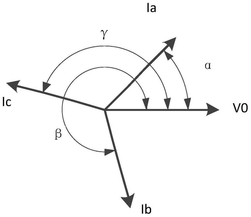
[0028] Definition: The current phase angle refers to the angular difference between the current flowing through the switch and the reference waveform. The sudden change of phase angle refers to the current phase angle changing over 90 degrees between the current cycle and the previous cycle. The installation direction of the current transformer of the relay protection device is unified. , define the load of the power supply to the busbar of this section as the positive direction.

[0029] S1: The relay protection device has a unique ID address in the whole network, and collects the three-phase current at the load / section switch according to the inherent sampling frequency;

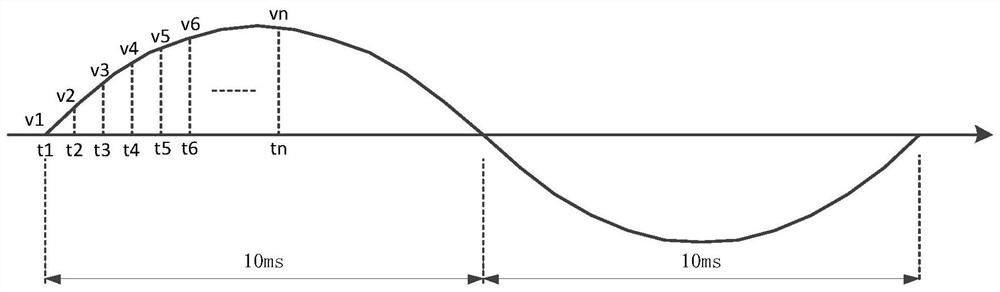
[0030] S2: The protection server sends the sampling data of the fixed power frequency waveform according to the sampling frequency ...


PUM


Abstract

The invention relates to a ring network power supply system fault location system based on communication injection waveforms. The location system is composed of a relay protection device installed at each load / section switch and a protection server communicating with each protection device. The server and the relay protection device use optical fiber for full-duplex communication, and one section of the busbar area is configured. This scheme can effectively reduce the scope of power outages, and the fault is isolated by tripping the switch closest to the fault point; this scheme has nothing to do with the number of power supplies, and can realize the radial single power supply network and the fault location of the multi-power ring power supply network and isolation.

Description

technical field [0001] The invention belongs to the field of fault location of intelligent power distribution technology, and in particular relates to a fault location and isolation method of a ring network power supply system based on a communication injection waveform. Background technique [0002] With the development of society, people have higher and higher requirements for the reliability of power supply, especially in important institutions such as hospitals and governments, and important independent power supply areas such as ships and camps. For special loads with particularly high safety and reliability requirements, the ring network power supply method is generally used, and the same load is supplied by multiple power points, which can be operated in parallel or in parallel. When the switching device is put into another power supply, the failure of one power supply will not affect the separate power supply of the intact power supply during parallel operation. How...

Claims


Application Information

Patent Timeline
Patent Type & Authority Patents(China)
IPC IPC(8): H02H1/00H02H7/26H02H7/28
CPCH02H1/0007H02H1/0061H02H1/0092H02H7/263H02H7/28
Inventor 李从飞田伟侯继海何龙陈凡
Owner 南京弘毅电气自动化有限公司
Why Eureka
Try Eureka