
Auxiliary positioning and pressing equipment applied to hook-type commutator production

A technology for auxiliary positioning and pressing equipment, which is applied in the direction of commutator manufacturing, motor generator connectors, etc., can solve problems such as low efficiency, and achieve the effect of ensuring efficiency

Active Publication Date: 2021-09-28
浙江利丰电器有限公司
View PDF9 Cites 0 Cited by
  • Summary
  • Abstract
  • Description
  • Claims
  • Application Information

AI Technical Summary

Problems solved by technology

[0002] The commutator, commonly known as the commutator, is a part of the DC permanent magnet series motor in order to allow the motor to continue to rotate. Structurally, the commutator is a circle surrounded by several contact pieces, which are respectively connected to each tap on the rotor. , the two electrodes connected outside are called brushes, and only two of them are in contact at the same time. The types of commutators can be roughly divided into two types, one is a slot-type diverter, and the other is a hook-type diverter. In the production process of the hook-type diverter, it is first manufactured by injection. When the basic structure is injected, it is usually possible to process the claw part of the hook-type commutator with ordinary stamping machine tools. However, in this process, the staff needs to manually load and unload. In order to ensure the shape of the stamped claws, it is necessary to manually adjust the position of the workpiece to ensure the shape of the stamped claws. less efficient

Method used


Image

  • Auxiliary positioning and pressing equipment applied to hook-type commutator production
  • Auxiliary positioning and pressing equipment applied to hook-type commutator production
  • Auxiliary positioning and pressing equipment applied to hook-type commutator production

Examples


Embodiment Construction

[0026] In order to make the objects, technical solutions, and advantages of the present invention more clear, the technical solutions in the embodiments in the embodiments will be described in contemplation in the accompanying drawings in the embodiment of the present invention. Obviously, the described embodiments are all embodiments of the invention, not all of the embodiments. Based on the embodiments of the present invention, those of ordinary skill in the art will belong to the scope of the present invention without all other embodiments obtained without creative labor.

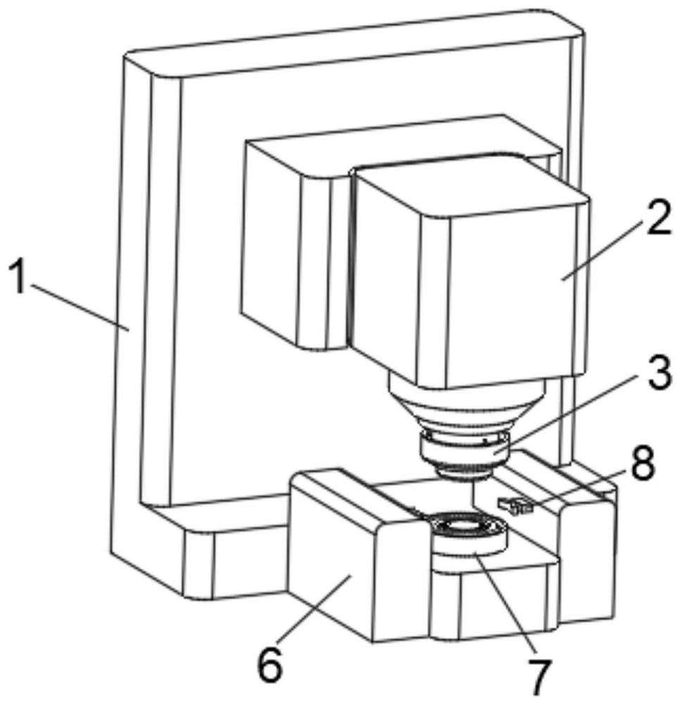
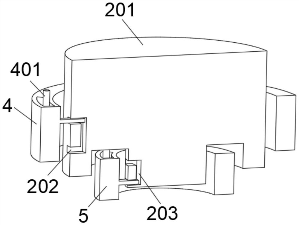
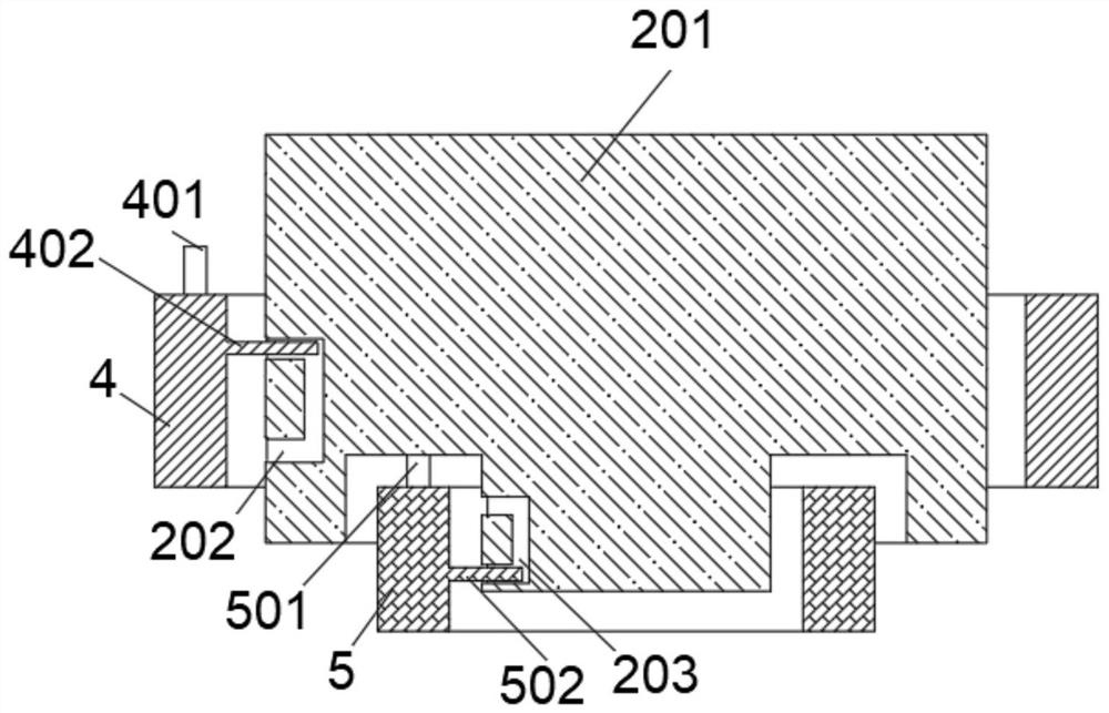
[0027] See Figure 1-8 , The present invention is applied to provide a hook-type commutator production apparatus auxiliary locating nip Example:

[0028] Applied to the hook-type commutator production nip auxiliary positioning apparatus including stamping apparatus body 2, and means for fixing the mount 2 punching apparatus body 1 comprises an output terminal 201 mounted on the apparatus body 2 is press-stamp...


PUM


Abstract

The invention relates to the technical field of hook-type commutator production equipment, in particular to auxiliary positioning and pressing equipment applied to hook-type commutator production. The equipment comprises a stamping equipment body, a mounting seat for fixing the stamping equipment body, and a stamping part adjusting module mounted at the output end of the stamping equipment body, and a bearing mechanism corresponding to the output end in position is arranged at the lower end of the stamping equipment body. Through an arranged auxiliary positioning assembly, a punching mechanism can be used as power, and the auxiliary positioning assembly is matched with an arranged moving block, an arranged sliding plate and other structures, so that a commutator to be punched is accurately positioned, and the punching efficiency is guaranteed. Through cooperative use of the samping piece adjusting module, stamping parts can be flexibly replaced according to actual stamping requirements.

Description

Technical field [0001] The present invention relates to production equipment commutator hook Field, particularly as applied to the hook-type commutator production equipment assisted positioning nip. Background technique [0002] Commonly known commutator commutator, is a permanent magnet DC series motor in order to enable a member of the motor continues to rotate down, the structure of the commutator contact piece is surrounded by several round, each tap are respectively connected to the rotor , two connected outer electrode called brushes in contact therewith, while only two of which are in contact with, the type of commutator can be divided into two types, one is a steering groove, one is hook diverter, in the hook diverter production process, first manufactured by way of injection pressure, injection pressure at the time of completion of the basic structure, usually with a normal punching machine for processing can be realized on the hook portion of the hook-type commutator, i...

Claims


Application Information

Patent Timeline
Patent Type & Authority Applications(China)
IPC IPC(8): H01R43/06
CPCH01R43/06H01R2201/10
Inventor 张余明
Owner 浙江利丰电器有限公司
Learn More