Anti-interference intelligent error correction communication system in complex electromagnetic environment
A technology for complex electromagnetic and communication systems, applied in the field of anti-interference intelligent error correction communication systems in complex electromagnetic environments, can solve problems such as increased difficulty in obtaining information, reduced equipment control reliability, and equipment command and control difficulties, and achieves enhanced error correction resistance. Interference effect, solve uneven force, ensure stability effect
- Summary
- Abstract
- Description
- Claims
- Application Information
AI Technical Summary
Problems solved by technology
Method used
Image
Examples
Embodiment 1
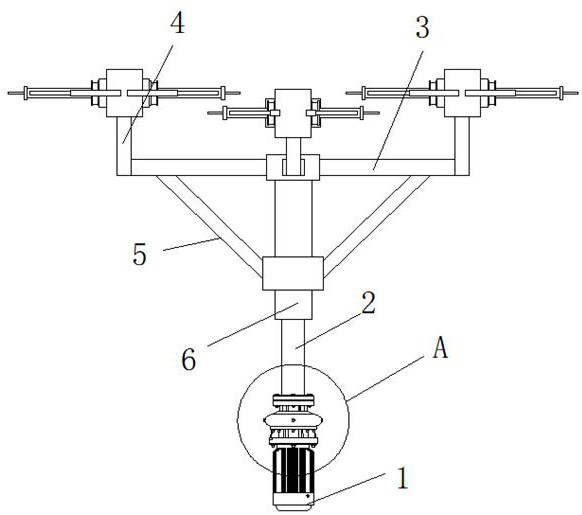
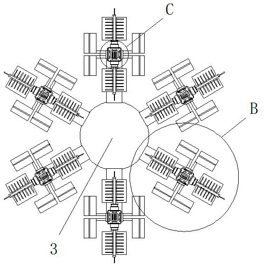
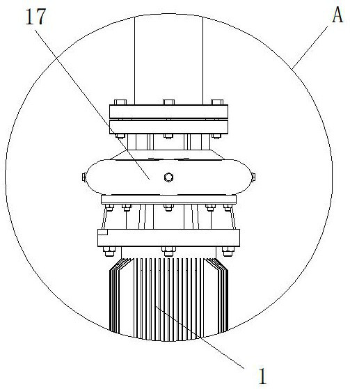
[0027] Embodiment 1: as figure 1 As shown, the complex electromagnetic environment anti-interference intelligent error correction communication system proposed by the present invention includes a drive motor 1, a bolt plate is installed at the bottom of the drive motor 1, and is connected to any plane by bolts, and the output end of the drive motor 1 is fixed by a flange Connected with a gearbox 17, the output end of the gearbox 17 is welded with a drive shaft 2, and the end of the drive shaft 2 away from the gearbox 17 is welded with a sleeve 6, the inside of the sleeve 6 is hollow, and the top of the sleeve 6 is welded with a turntable 3. Six fixed rods 4 are evenly welded around the turntable 3. The end of the fixed rod 4 away from the turntable 3 is welded with a sealed box 16. The inner cavity of the sealed box 16 is provided with mutually symmetrical mounting seats 14, and the mounting seats 14 are mutually symmetrical. A support frame 15 is welded on the adjacent sides,...
Embodiment 2
[0028] Embodiment 2: as figure 2 , Figure 4 As shown, the output end of the servo motor 12 is welded with a rotating shaft 13, and the end of the rotating shaft 13 away from the servo motor 12 is welded with a dust cover 11 that penetrates and extends to the outside of the sealed box 16, and the dust cover 11 is located outside the sealed box 16. An antenna main rod 10 is welded at one end of each of the antenna main rods, and the outer ring of the antenna main rod 10 is uniformly welded with antenna keels arranged in a rectangular array, and the end of the antenna keel away from the antenna main rod 10 is welded with a frequency hopping main antenna 9.
Embodiment 3
[0029] Embodiment 3: as figure 1 , Figure 4 As shown, the sealed box 16 is welded with two antenna sub-rods 8 on the side walls symmetrical to each other with the midpoint of the fixed rod 4, and the end of the antenna sub-rod 8 away from the sealed box 16 is welded with a frequency hopping sub-antenna 7 , the upper surface of the frequency hopping sub-antenna 7 is provided with a filter collector, and the end of the antenna main rod 10 away from the sealed box 16 is welded with a signal receiving box, and the end of the signal receiving box away from the antenna main rod 10 is provided with a signal pin.
PUM
 Abstract
Description
Claims
Application Information
 - R&D
- Intellectual Property
- Life Sciences
- Materials
- Tech Scout
- Unparalleled Data Quality
- Higher Quality Content
- 60% Fewer Hallucinations
Browse by: Latest US Patents, China's latest patents, Technical Efficacy Thesaurus, Application Domain, Technology Topic, Popular Technical Reports.
© 2025 PatSnap. All rights reserved.Legal|Privacy policy|Modern Slavery Act Transparency Statement|Sitemap|About US| Contact US: help@patsnap.com


