
Test device and test system for electronic components

A technology for testing devices and electronic components, which is applied to electronic circuit testing, measuring devices, measuring device casings, etc., can solve problems such as compression and deformation of the lower end plate of the rack, and achieve the effect of reducing force and preventing deformation.

Active Publication Date: 2021-12-07
HANGZHOU CHANGCHUAN TECH CO LTD
View PDF0 Cites 0 Cited by
  • Summary
  • Abstract
  • Description
  • Claims
  • Application Information

AI Technical Summary

Problems solved by technology

[0003] In view of this, it is necessary to provide a test device and a test system for electronic components, to solve the problem that the lower end plate of the frame will be deformed by the indenter assembly during the working process of the existing test device

Method used


Image

  • Test device and test system for electronic components
  • Test device and test system for electronic components
  • Test device and test system for electronic components

Examples


Embodiment 1

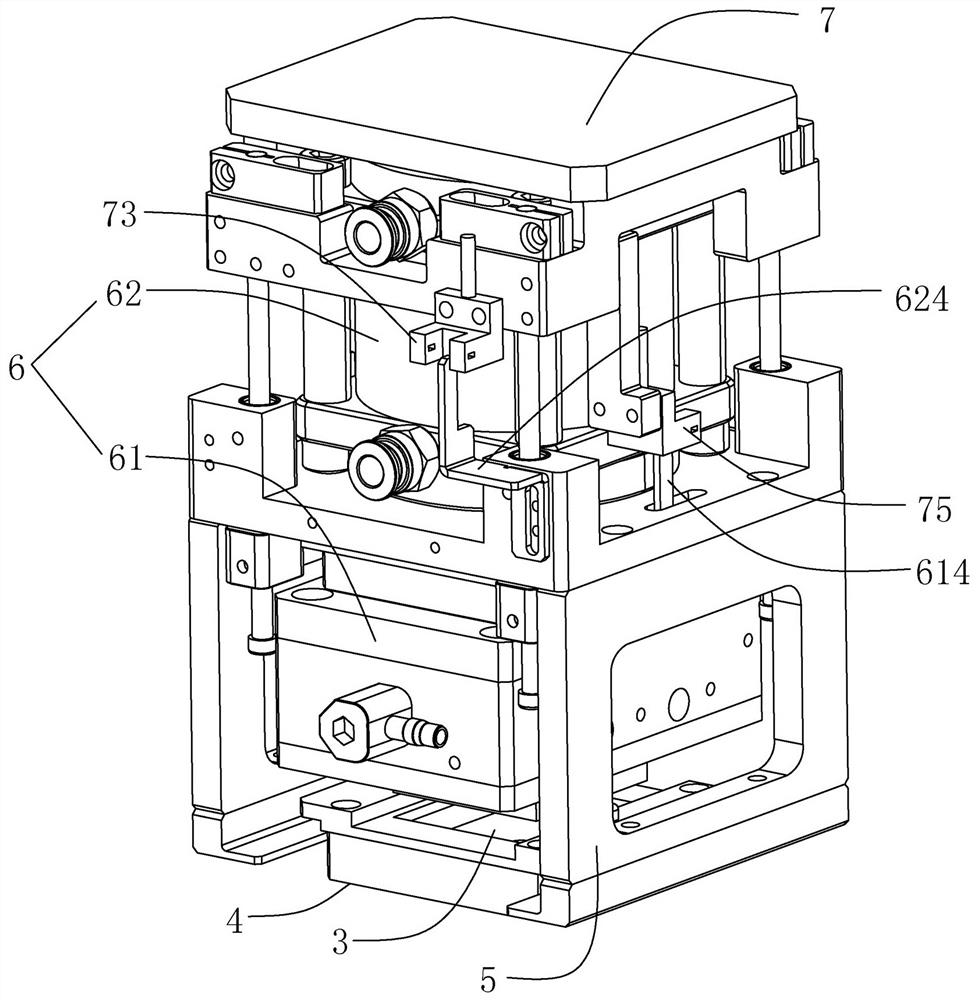
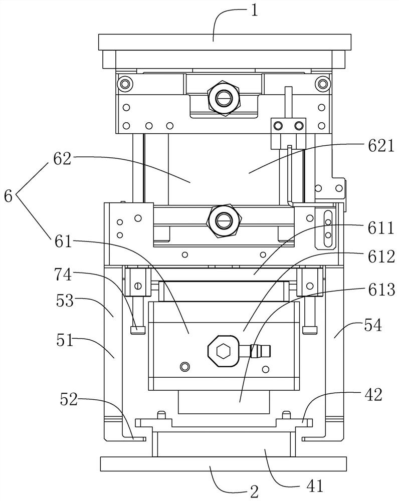
[0041] Embodiment 1, the force balance bracket 5 is connected to the indenter assembly 6 through an intermediate piece (not shown in the figure), and when the indenter assembly 6 crimps the electronic component 3 toward the loading seat 4, the indenter assembly 6 can drive the intermediate piece to connect the force balance One end of the bracket 5 moves away from the loading seat 4 , so that the force balance bracket 5 can move away from the loading base 4 and apply a force on the loading base 4 away from the lower end plate 2 . The above-mentioned middle piece acts as a lever, and the pressure head assembly 6 drives one end of the middle piece to move toward the direction of the loading seat 4, while the other end of the middle piece moves in the opposite direction, thereby driving the force balance bracket 5 to move away from the loading The direction of the seat 4 moves and exerts a force on the loading seat 4 away from the lower end plate 2 .

Embodiment 2

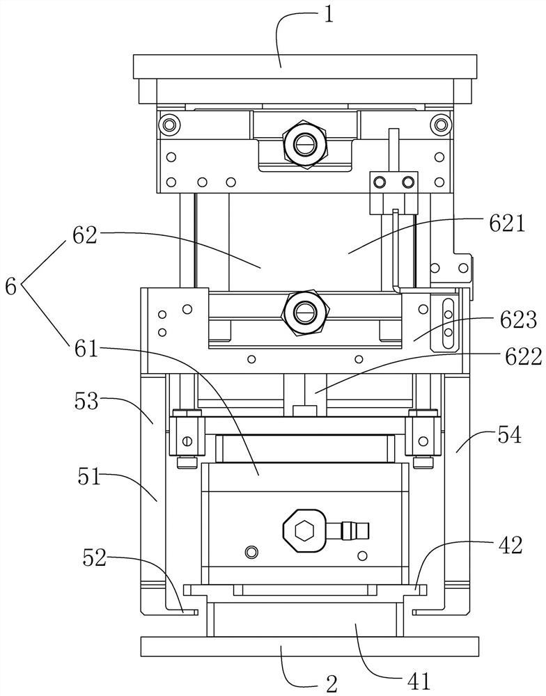
[0042] Embodiment two, such as Figure 1-Figure 4 As shown, the ram assembly 6 includes a power assembly 62 and a crimping assembly 61, the crimping assembly 61 is movably connected to the power assembly 62, and the power assembly 62 can drive the crimping assembly 61 to move toward or away from the carrier 4 to press connected to or away from the electronic component 3, the force balance bracket 5 is fixedly connected to the power assembly 62, when the crimping assembly 61 abuts against the electronic component 3, the crimping assembly 61 can reversely push the power assembly 62 to move away from the lower end plate 2, And the force balance bracket 5 can hook the loading seat 4 and apply a force to the loading base 4 away from the lower end plate 2 .

[0043] Specifically, such as Figure 5 As shown, the power assembly 62 includes a driving cylinder. The driving cylinder includes a cylinder body 621 and a piston 622. One end of the piston 622 is movably connected to the cyli...


PUM


Abstract

The invention relates to a test device and a test system for electronic components. The test device is installed on a frame, the frame has a lower end plate, and the test device includes a pressure head assembly, an object seat and a force balance support. The object seat is installed on the lower end plate, and the object seat is used to place the electronic components. The indenter assembly can move toward the object seat to crimp the electronic components, or the indenter assembly can move away from the object seat. The force balance bracket cooperates with the load seat, and the force balance bracket can hook the load seat and apply a force away from the lower end plate to the load seat. The test device and test system for electronic components provided by the invention solve the problem that the lower end plate of the frame will be deformed under pressure caused by the indenter assembly during the working process of the existing test device.

Description

technical field [0001] The invention relates to the technical field of chip manufacturing, in particular to a test device and a test system for electronic components. Background technique [0002] A testing device for testing chips is usually mounted on a frame, and the frame has an upper end plate and a lower end plate, and chips to be tested are placed on the lower end plate of the frame. The testing device includes an indenter assembly and an object holder. The object seat is installed on the lower end plate, and the object seat is used for placing chips or other electronic components, and the indenter assembly can move toward the object seat to crimp the chips. When the indenter assembly exerts pressure on the chip, the pressure will be transmitted to the lower end plate through the object holder, thereby causing the lower end plate to deform to a certain extent. The above-mentioned deformation is slight in a short time, but under the continuous action of the indenter ...

Claims


Application Information

Patent Timeline
Patent Type & Authority Patents(China)
IPC IPC(8): G01R1/04G01R31/00G01R31/28
CPCG01R1/0416G01R31/00G01R31/2886G01R31/2891
Inventor 徐铭阳胡冲鲍军其王昭敦
Owner HANGZHOU CHANGCHUAN TECH CO LTD
Learn More