
Airborne drilling and splitting combined machine

A combined machine and mounting frame technology, which is applied to drilling equipment and methods, discharge machinery, earthwork drilling and mining, etc. It can solve the problem of stone materials with a large surface inclination that cannot be mined, the self-heaviness of drilling rigs and hydraulic splitting machines, and manual handling. Inconvenience and other problems, to achieve the effect of easy purchase and maintenance, controllable turning angle and mature structure

Pending Publication Date: 2021-09-28
JIANGSU ZHONGJI MINE EQUIP
View PDF0 Cites 2 Cited by
  • Summary
  • Abstract
  • Description
  • Claims
  • Application Information

AI Technical Summary

Problems solved by technology

However, in the process of mining stone with a hydraulic splitting machine, it is necessary to manually operate the drilling rig to drill holes on the working face, and then carry the hydraulic splitting machine to the drilling hole to split the rock. The weight of the drilling rig and the hydraulic splitting machine Larger, inconvenient for manual handling, and because the work of the hydraulic splitting machine requires manual positioning, it is impossible to mine stones with a large surface inclination. In addition, for large stones, multiple drilling and multi-machine splitting are required, while drilling and splitting The interval between the two processes of splitting is long and the efficiency is low. Therefore, it is necessary to design an airborne drilling and splitting combination machine

Method used


Image

  • Airborne drilling and splitting combined machine
  • Airborne drilling and splitting combined machine
  • Airborne drilling and splitting combined machine

Examples


Embodiment 1

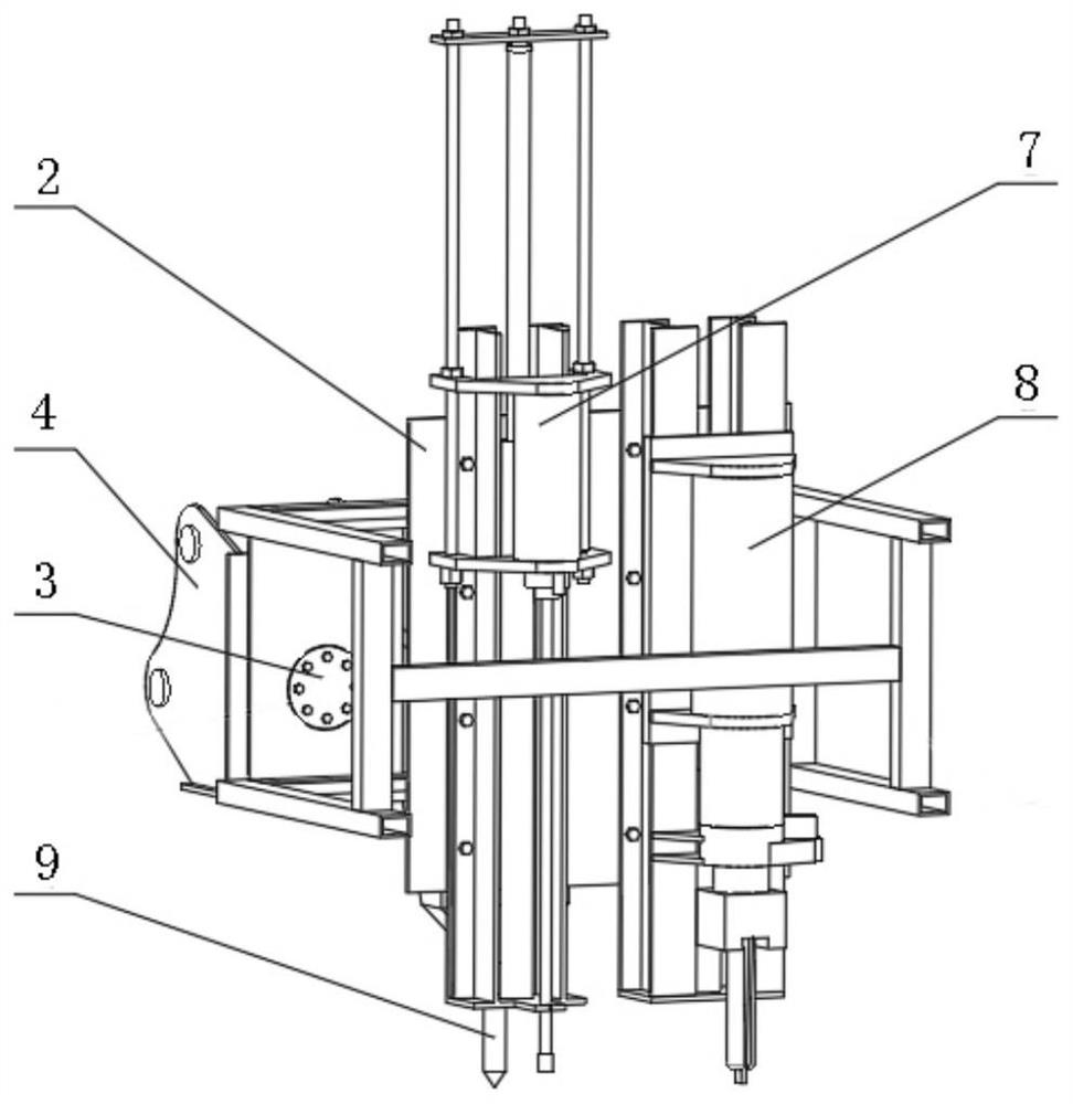
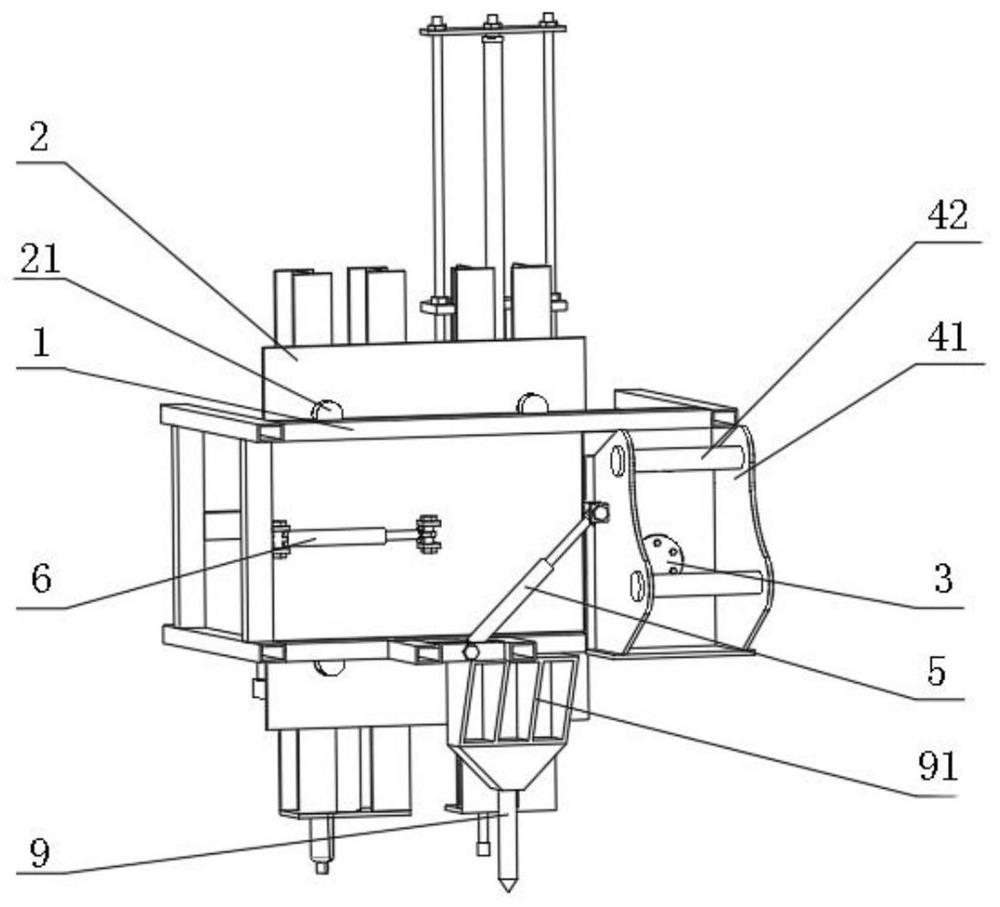
[0034] In this embodiment, an airborne drilling and splitting combination machine is designed, which includes a mounting frame 1 and a transposition plate 2. The mounting frame 1 is provided with a slewing support 3, and the slewing support 3 is a bearing. The slewing support 3 is connected with hanging lugs. 4. The slewing ring 3 is made of bearings, which have a mature structure and are easy to purchase and maintain. The inner ring and outer ring of the bearing are relatively fixed on the mounting frame 1 and the mounting lug 4 respectively, and the mounting lug 4 is formed by a square grooved lug plate 41 and the trunnion 42 fixed on the groove wall of the lug plate 41, which can make the whole equipment more convenient to hang on other movable construction machinery such as excavators, and the slewing bearing 3 is connected to the groove bottom of the lug plate 41 , the hanging lug 4 is used to hang on movable construction machinery such as excavators, and a rotation degree...

Embodiment 2

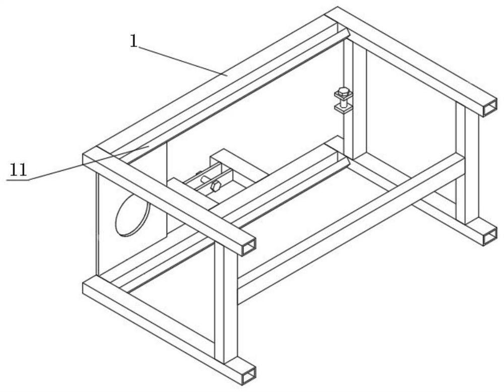
[0037] In this embodiment, an airborne drilling and splitting combination machine is designed, which includes a mounting frame 1 and a transposition plate 2. The mounting frame 1 is spliced ​​by rod-shaped profiles, and supporting guardrails are provided on both sides of the mounting frame 1. The installation frame 1 is provided with a slewing bearing 3, and the slewing bearing 3 is connected with a hanging lug 4. The slewing bearing 3 is preferably a single-row cross roller type, with a mature structure, easy to purchase and maintain, the inner race of the slewing bearing 3 and the hanging The ear 4 is connected by bolts, the outer race is connected with the mounting frame 1 by bolts, the mounting frame 1 can rotate around the slewing support 3, and the hanging lug 4 is fixed in the groove of the hanging lug plate 41 by a square groove-shaped lug plate 41 The hanging trunnion 42 of the wall is composed of two hanging trunnions 42, and the two hanging trunnions 42 are parallel ...

Embodiment 3

[0039] In this embodiment, an airborne drilling and splitting combination machine is designed, which includes a mounting frame 1 and a transposition plate 2. The mounting frame 1 is welded by tubular profiles, and the mounting frame 1 is provided with a slewing support 3, which 3 is connected with hanging lug 4, the slewing bearing 3 is preferably a single-row cross roller type, with a mature structure, easy to purchase and maintain, the outer race of the slewing bearing 3 and the lug 4 are connected by bolts, and the inner race and installation The frame 1 is connected by bolts, and the mounting frame 1 can rotate around the slewing bearing 3. The hanging lug 4 is composed of a square groove-shaped hanging lug plate 41 and a hanging trunnion 42 fixed on the groove wall of the hanging lug plate 41. The hanging trunnion 42 is provided with two, two hanging trunnions 42 are parallel to each other, and the distance from the bottom of the groove of the hanging lug plate 41 is differe...


PUM


Abstract

The invention discloses an airborne drilling and splitting combined machine. The airborne drilling and splitting combined machine comprises a mounting frame and a transposition plate, wherein the mounting frame is provided with a slewing bearing; the slewing bearing is connected with a hanging lug; a rotation degree control device is arranged between the hanging lug and the mounting frame; the rotation degree control device is linked with the slewing bearing; rails are oppositely arranged at the upper end and the lower end of the mounting frame; each rail is provided with at least two rail wheels; wheel shafts of the rail wheels are relatively fixed with the transposition plate; a distance control device is arranged between the transposition plate and the mounting frame; the transposition plate is fixedly provided with a drilling module and a splitting module, and the working directions of the drilling module and the splitting module are vertical to the rails; and the mounting frame is provided with a positioning rod, and the working direction of the positioning rod is vertical to the rails. The transposition plate, the rotation degree control device and the distance control device are arranged so that the drilling module and the splitting module can realize controllable selection of angles and distances, and furthermore, the technical effect of efficiently and automatically mining stones with different inclination degrees on the surfaces can be realized.

Description

technical field [0001] The invention belongs to the technical field of rock drilling and splitting machines, in particular to an airborne drilling and splitting combined machine. Background technique [0002] my country has the largest construction market in the world, and the construction stone industry has developed rapidly in recent years. According to statistics from the China Stone Association, my country's total stone exports will reach US$6.54 billion in 2020. my country is rich in stone ore reserves, and the mining areas are all over the country. Some medium and large enterprises have realized large-scale and mechanized quarrying, but small enterprises still have problems such as backward mining technology, low degree of mechanization, and low mining efficiency. At present, domestic stone mining methods mainly include: manual mining, drilling and blasting, and mechanical mining. Among them, manual mining is inefficient and unable to mine large stones, and is currentl...

Claims


Application Information

Patent Timeline
IPC IPC(8): E21B7/04E21B15/04E21B3/02E21C37/02
CPCE21B7/04E21B15/04E21B3/02E21C37/02
Inventor 江红祥刘送永杜迈郝尚清曹程溪
Owner JIANGSU ZHONGJI MINE EQUIP
Learn More