Sponge city roof garden water storage and drainage device

A sponge city and drainage device technology, applied to roof drainage, water supply devices, watering devices, etc., can solve problems such as excessive water accumulation, achieve the effect of increasing utilization rate and improving drainage capacity

Pending Publication Date: 2021-09-28
徐秀珍
View PDF0 Cites 3 Cited by
  • Summary
  • Abstract
  • Description
  • Claims
  • Application Information

AI Technical Summary

Problems solved by technology

[0004] The object of the present invention is to solve the shortcomings in the prior art, and propose a water storage and drainage device for the roof garden of the sponge city. During use, the device can automatically store water when the rain is small, and it can automatically store water when the rain is relatively small. When the large water storage is slow, the excess rainwater will be discharged. When the rain is too heavy, the pipeline will not meet the drainage requirements, so as to avoid excessive water accumulation and clean up the garbage at the opening of the rectangular slot. Avoid slot clogging

Method used


Image

  • Sponge city roof garden water storage and drainage device
  • Sponge city roof garden water storage and drainage device
  • Sponge city roof garden water storage and drainage device

Examples


Embodiment 1

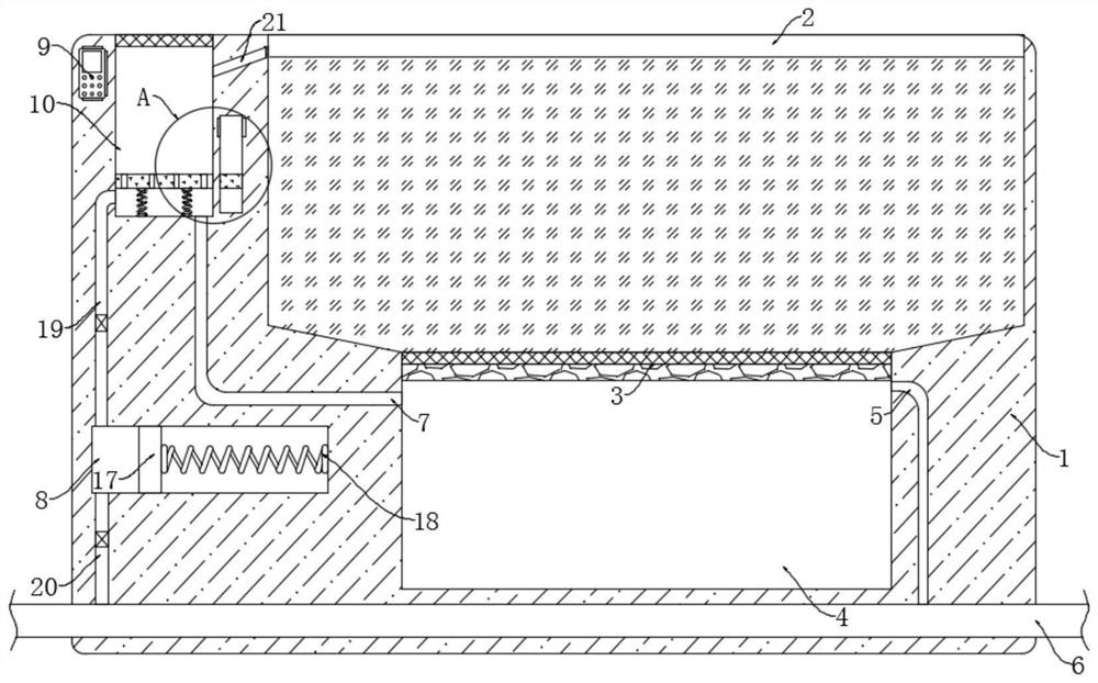
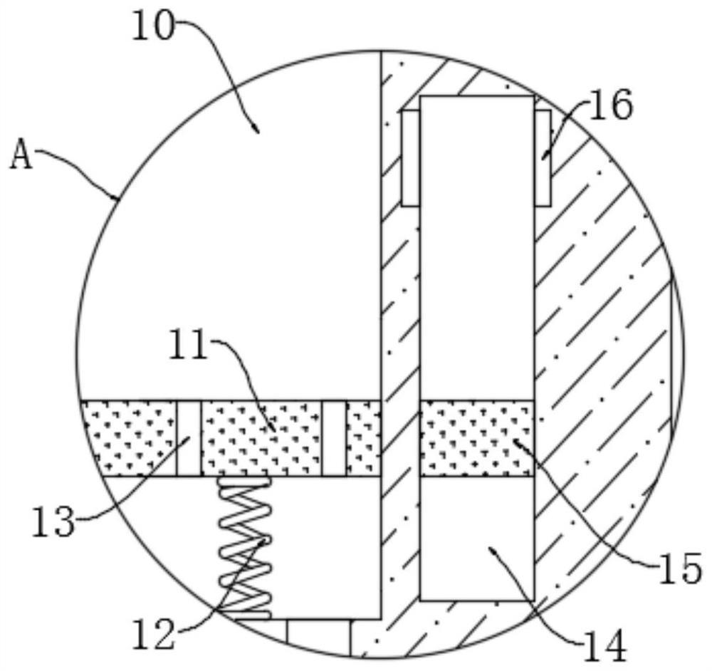
[0022] refer to Figure 1-2 , a water storage and drainage device for a sponge city roof garden, comprising a housing 1, the upper end of the housing 1 is provided with a planting tank 2, the inner bottom of the planting tank 2 is provided with a water storage chamber 4, and the inner top of the water storage chamber 4 is provided with The filter layer 3, the filter layer 3 is composed of a filter screen and an activated carbon layer, the filter screen is located above the activated carbon layer, the filter layer 3 can filter and absorb the impurities in the water infiltrated by the soil, and the upper end of the shell 1 is provided with a rectangular groove 10, The notch of the rectangular groove 10 is provided with a first mesh plate to prevent the garbage from entering the rectangular groove 10 and causing pipeline blockage. 8 is located on the left side of the water storage chamber 4, the housing 1 is provided with a sewage pipe 6, the sewage pipe 6 is connected to the mun...

Embodiment 2

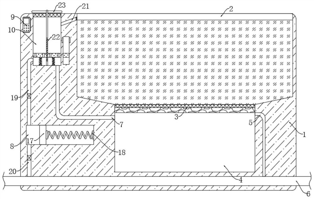
[0033] refer to image 3 , the difference between this embodiment and Embodiment 1 is that a rotating rod 22 is provided in the rectangular groove 10, and the rotating rod 22 is rotationally connected with the inner bottom of the rectangular groove 10. The rotating rod 22 is provided with a threaded layer, and the floating plate 11 and Part of the threaded layer of the rotating rod 22 is threaded, and the upper end of the rotating rod 22 extends to the outside and a plurality of stirring blades 23 are installed along its circumference.

[0034] In this embodiment, in the process of moving up and down of the floating plate 11, it will drive the rotating rod 22 to rotate. Some sundries are swept to the outside of the notch, thereby avoiding that the notch of the rectangular groove 10 is blocked by the sundries and the situation that accumulated water cannot be discharged takes place.

[0035] Compared with the prior art, the up and down movement of the floating plate 11 will dr...


PUM


Abstract

The invention discloses a sponge city roof garden water storage and drainage device. The device comprises a shell, wherein a planting groove is formed in the upper end of the shell, a water storage cavity is formed in the inner bottom of the planting groove, a filtering layer is arranged on the inner top of the water storage cavity, a rectangular groove is formed in the upper end of the shell, a first net plate is arranged at a groove opening of the rectangular groove, the rectangular groove is located in the left side of the planting groove, a reciprocating cavity is formed in the shell, and is located in the left side of the water storage cavity, a sewage pipe is arranged in the shell, and a power source is arranged in the shell. In the use process of the device, when the rain potential is small, water can be automatically stored, when the rain potential is large, water storage is slow, redundant rainwater can be drained, when the rain potential is large, a pipeline cannot meet the drainage requirement, active drainage is carried out, the phenomenon that too much water is gathered is avoided, garbage at the groove opening of the rectangular groove can be removed, and the groove opening is prevented from being blocked.

Description

technical field [0001] The invention relates to the technical field of sponge cities, in particular to a water storage and drainage device for roof gardens of sponge cities. Background technique [0002] The sponge city is also known as a water elastic city. When it rains, it absorbs, stores, infiltrates, and purifies rainwater. When needed, it releases and uses the stored water to realize the free migration of rainwater in the city. Because the roof garden can It plays a good role in water storage and rainwater utilization, and has been widely used in the construction of sponge cities. However, the existing roof gardens still have the following problems: [0003] In the actual use of existing roof gardens, water can be stored when the rain is small. Due to subsequent irrigation, when the rain is heavy and the soil absorbs water to a saturated state, excess water will accumulate in the soil, which is easy to Cause the roots of the plants to rot and cause death, and the soil...

Claims


Application Information

Patent Timeline
IPC IPC(8): E04D13/00E04D13/04E03B3/02C02F9/02A01G9/02A01G25/02
CPCE04D13/00E04D13/04E04D13/0404E03B3/02C02F1/001C02F1/283A01G9/02A01G25/02E04D2013/0495Y02A20/108
Inventor 徐秀珍
Owner 徐秀珍
Why Eureka
Try Eureka