
Intelligent over-temperature automatic power-off control device for textile motor

A technology of automatic power-off and control devices, which is applied in the direction of electromechanical devices, electric components, and control of mechanical energy, can solve problems such as temperature rise, air-conditioning cooling temperature can not keep up, textile motor damage, etc., and achieve the effect of reducing production efficiency loss

Active Publication Date: 2021-09-24
南通三田纺织有限公司
View PDF6 Cites 0 Cited by
  • Summary
  • Abstract
  • Description
  • Claims
  • Application Information

AI Technical Summary

Problems solved by technology

[0002] Iron loss refers to the sum of hysteresis loss and eddy current loss per unit mass of ferromagnetic materials in alternating and pulsating magnetic fields. In textile production workshops, larger processing machines, such as warp machines, require larger textile There are generally dozens of sets in the textile workshop. Often, the textile motor generates more heat and the temperature in the workshop rises. The cooling temperature of the air conditioner in the workshop cannot keep up with the heat generated by the textile motor. It will cause great harm, and the heat generated at the same time will also affect the health of the operator, and shutting down the textile motor with too high working temperature to cool down naturally or artificially, which will be extremely harmful to textile factories that work in two shifts day and night. Therefore, it is very useful to design an intelligent over-temperature automatic power-off control device for textile motors that cools down the textile motor when it is working, and enables the spare shaft to continue to work when the temperature is too high. necessary

Method used


Image

  • Intelligent over-temperature automatic power-off control device for textile motor
  • Intelligent over-temperature automatic power-off control device for textile motor
  • Intelligent over-temperature automatic power-off control device for textile motor

Examples


Embodiment Construction

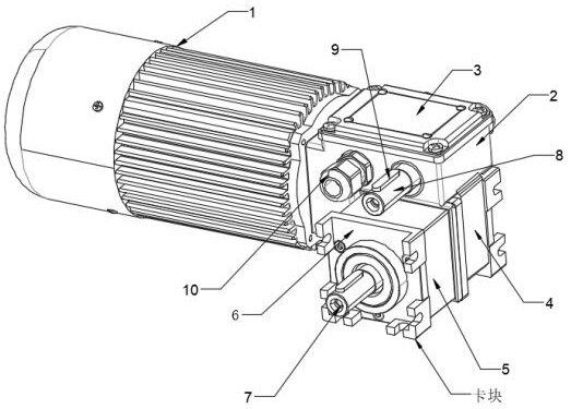
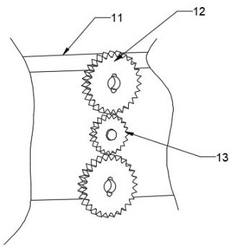
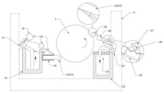
[0028] The following will clearly and completely describe the technical solutions in the embodiments of the present invention with reference to the accompanying drawings in the embodiments of the present invention. Obviously, the described embodiments are only some, not all, embodiments of the present invention. Based on the embodiments of the present invention, all other embodiments obtained by persons of ordinary skill in the art without making creative efforts belong to the protection scope of the present invention.

[0029] see Figure 1-5 , the present invention provides a technical solution: an intelligent over-temperature automatic power-off control device for textile motors, including an intelligent temperature control system, a temperature control machine 1 and a textile base 11, characterized in that: the temperature control machine 1 includes Power supply machine, one side of the textile base 11 is provided with a mechanical claw, the temperature control machine 1 i...


PUM


Abstract

The invention provides an intelligent over-temperature automatic power-off control device for a textile motor. The device comprises an intelligent temperature control system, a temperature control machine and a spinning base station, and is characterized in that the temperature control machine comprises a power supply machine, a mechanical claw is arranged on one side of the spinning base station, the temperature control machine is fixed on one side of the spinning base station, a driven wheel is connected with a center bearing of the side, close to the temperature control machine, of the spinning base table, driving wheels are connected with the upper end and the lower end of the driven wheel in a meshed mode, one side of each driving wheel is connected with the spinning base table through a bearing, a concave hole is formed in the center of the other side of each driving wheel, a factory-shaped auxiliary shell is welded to the right end of the temperature control machine, the lower end of the factory-shaped auxiliary shell is connected with an output shell in a meshed mode through a screw, an observation cover is riveted to the center of the top end of the factory-shaped auxiliary shell, and a first hole is formed in one end of the factory-shaped auxiliary shell. The device has the advantages that the textile motor is cooled when working, and a standby shaft is started to work continuously when the temperature is too high.

Description

technical field [0001] The invention relates to the technical field of textile motors, in particular to an intelligent over-temperature automatic power-off control device for textile motors. Background technique [0002] Iron loss refers to the sum of hysteresis loss and eddy current loss per unit mass of ferromagnetic materials in alternating and pulsating magnetic fields. In textile production workshops, larger processing machines, such as warp machines, require larger textile There are generally dozens of sets in the textile workshop. Often, the textile motor generates more heat and the temperature in the workshop rises. The cooling temperature of the air conditioner in the workshop cannot keep up with the heat generated by the textile motor. It will cause great harm, and the heat generated at the same time will also affect the health of the operator, and shutting down the textile motor with too high working temperature to cool down naturally or artificially, which will b...

Claims


Application Information

Patent Timeline
Patent Type & Authority Applications(China)
IPC IPC(8): H02K11/25H02K11/30H02K11/20H02K11/21H02K9/04H02K7/00H02K5/10
CPCH02K11/25H02K11/30H02K11/20H02K11/21H02K9/04H02K7/003H02K5/10H02K2213/06
Inventor 苏燕范建勋
Owner 南通三田纺织有限公司
Learn More