
A water floating aeration device

A technology for aeration devices and water areas, applied in biological treatment devices, biological water/sewage treatment, water/sludge/sewage treatment, etc., can solve problems such as internal equipment damage, immersion, and inability to smoothly aerate water areas, and achieve The effect of prolonging the contact time, facilitating transportation and adjustment, improving the scope of use and the convenience of use

Active Publication Date: 2022-04-05
宁波碧城生态科技有限公司
View PDF4 Cites 0 Cited by
  • Summary
  • Abstract
  • Description
  • Claims
  • Application Information

AI Technical Summary

Problems solved by technology

[0005] Aiming at the deficiencies of the prior art, the present invention provides a water area floating aeration device, which solves the problem that the existing water area floating aeration device is submerged in the water area due to insufficient length during use, and cannot perform water area aeration smoothly. operation, and the long-term injection of water flow is likely to cause damage to internal equipment

Method used


Image

  • A water floating aeration device
  • A water floating aeration device
  • A water floating aeration device

Examples


Embodiment 1

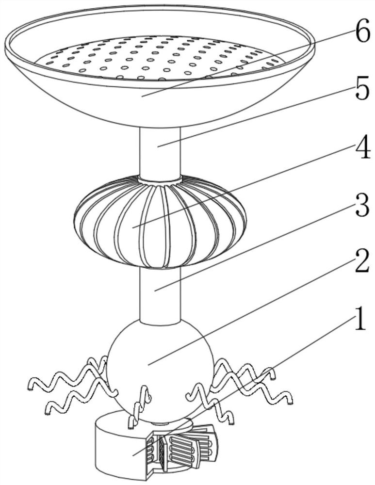
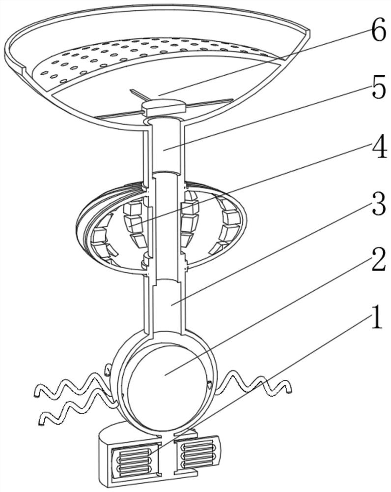
[0044] see Figure 1-6 , the present invention provides a technical solution: a water area floating aeration device, specifically comprising:

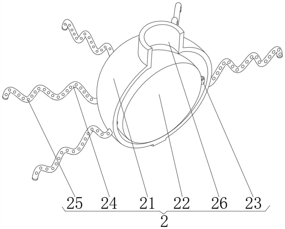
[0045] The water flow device 1, the water flow device 1 has a columnar body, and an air supply device 2 installed on the top of the columnar body, and a transmission air rod 3 installed on the top of the air supply device 2, and a floating device 4 installed on the top of the transmission air rod 3, and The air inlet pipe 5 installed on the top of the floating device 4, and the air inlet device 6 installed on the top of the air inlet pipe 5, the air delivery device 2 includes:

[0046] Ventilation ball shell 21, the ventilating ball shell 21 has a spherical shell, and a counterweight ball 22 installed at the bottom of the spherical shell inner cavity, and a through hole 23 provided at the middle and lower position of the outer surface of the spherical shell, and installed in the through hole 23 The air outlet hose 24 on the inner surf...

Embodiment 2

[0058] see Figure 1-6 , on the basis of Embodiment 1, the present invention provides a technical solution: a method for using a water area floating aeration device: Step 1: Adjust the mass and size of the counterweight ball 22, and rotate the air intake pipe 5 so that Trachea 5 is vertically adjusted on the surface of inner coil 41, and then it is sunk in the water area:

[0059] Step 2: the buoyancy generated by the ellipsoid plate 43 and the spherical cover 61 makes the top of the device on the water surface;

[0060] Step 3: The flow of water will drive the water flow plate 14 and the ellipsoidal plate 43 to rotate, so that the effect coil 15 and the magnetic block 45 will rotate accordingly, and cooperate with the induction coil in the magnetic circular plate 12 and the inner spiral tube 41 respectively. Electromagnetic conversion to supply energy for equipment;

[0061] Step 4: The electric energy is transmitted through the energy column 13, the transmission air rod 3 ...


PUM


Abstract

The invention discloses a water area floating aeration device, which specifically includes: a water flow device, an air supply device installed on the top of the columnar body, a floating device installed on the top of the air transmission rod, and an air intake pipe installed on the The air intake device at the top, the air supply device includes: a ventilating ball shell, and a weight ball installed at the bottom of the inner cavity of the spherical housing, and a through hole is opened at the middle and lower position of the outer surface of the spherical housing, and is installed on the The air outlet hose on the inner surface of the through hole, and the air bubble holes opened on the front and back of the air outlet hose, the invention relates to the technical field of environmental protection. Through the setting of the counterweight ball, it cooperates with the floating device to adjust the overall depth of the equipment in the water, avoiding the overall immersion of the equipment and ensuring that the bottom of the equipment is in contact with the water flow at the bottom of the water, which facilitates the smooth progress of the aeration work. At the same time, the wave-shaped air outlet hose resists foreign objects and protects the equipment.

Description

technical field [0001] The invention relates to the technical field of environmental protection, in particular to a water area floating aeration device. Background technique [0002] Due to the difference of the main pollution in the water body, the remediation methods are also different. When the pollutants are mainly organic pollutants, by controlling the pollution source, clearing the pollutants in the river, and turning the oxygen in the air into dissolved oxygen in the water through aeration method, the aerobic bacteria and aquatic organisms in the water can reproduce and grow, and gradually establish the water environment. The biological chain, and then assisting river bottom dredging, adding flocculants, and planting aquatic plants can completely restore the polluted water body. [0003] During the use of the existing water area floating aeration device, it is not long enough to be submerged in the water area, so the operation of the water area aeration cannot be car...

Claims


Application Information

Patent Timeline
Patent Type & Authority Patents(China)
IPC IPC(8): C02F3/02B01D46/10
CPCC02F3/02B01D46/103C02F2203/006Y02W10/10
Inventor 程春龙
Owner 宁波碧城生态科技有限公司
Learn More