
Real-time cutter detection device for machining center and detection method thereof

A real-time detection and processing center technology, applied in the direction of manufacturing tools, metal processing equipment, metal processing machinery parts, etc., can solve the problems of difficult tool wear degree detection, part size deviation, processing efficiency, etc., to ensure quality and improve Product accuracy, the effect of ensuring accuracy

Pending Publication Date: 2021-09-24
NANJING UNIV OF SCI & TECH
View PDF7 Cites 2 Cited by
  • Summary
  • Abstract
  • Description
  • Claims
  • Application Information

AI Technical Summary

Problems solved by technology

[0002] During the use of existing tools, it is difficult to detect the wear degree of the tool. When the wear degree of the tool is too large (especially during finishing), there will often be deviations in the size of the subsequent processing parts, and a large number of scrapped parts will easily be generated.
[0003] For this reason, the machine operator needs to periodically remove the tool from the machining center for inspection, which is not only cumbersome to operate, but also has a great impact on the processing efficiency, and is inconvenient in actual use

Method used


Image

  • Real-time cutter detection device for machining center and detection method thereof
  • Real-time cutter detection device for machining center and detection method thereof
  • Real-time cutter detection device for machining center and detection method thereof

Examples


Embodiment 1

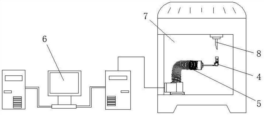
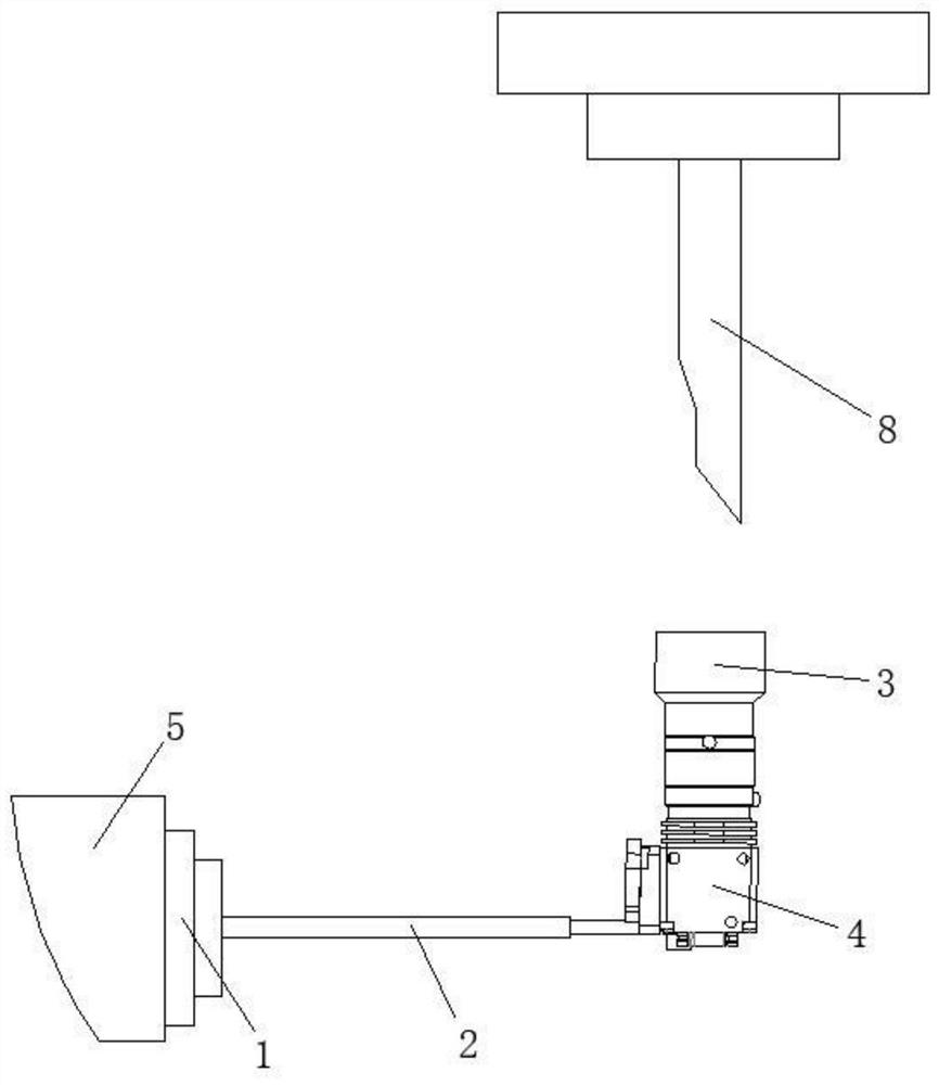
[0028] Embodiment 1: as figure 1 , 2 , 3, a tool real-time detection device and detection method for a machining center, including a collection area 7, the collection area 7 is provided with an in-position detection module and a signal transmission module, the tool 8 is suitable for running to The collection area 7, the in-position detection module includes a soft robotic arm 5, the end of the soft robotic arm 5 is provided with a visual image acquisition system, and the visual image acquisition system is suitable for collecting image information of a tool; The detection device also includes an image processing module 6, and the signal transmission module is suitable for transmitting the information collected by the visual image acquisition system to the image processing module 6; the image processing module 6 includes a damage assessment unit, and the damage The evaluation unit is suitable for comparing and evaluating the image information with preset information; the image ...

Embodiment 2

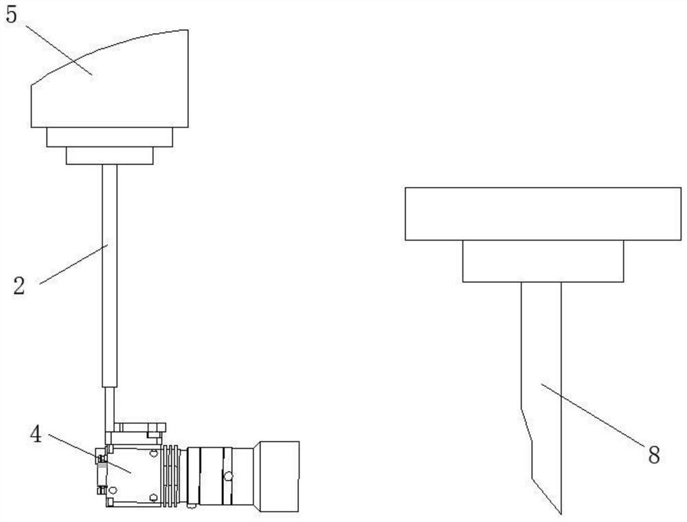
[0038] Embodiment 2: as figure 2 , 3 As shown, a camera support 2 is also arranged between the connecting piece 1 and the macro camera module 4 .

[0039] Through the setting of the camera support 2, it is convenient to adjust the initial angle of the camera, so as to ensure that the soft robotic arm 5 can accurately direct the shooting direction of the macro camera module 4 towards the specified direction.


PUM


Abstract

The invention discloses a real-time cutter detection device for a machining center, which comprises an acquisition area, an in-situ detection module is arranged in the acquisition area, the in-situ detection module comprises a soft mechanical arm, and a visual image acquisition system is arranged at the end part of the soft mechanical arm; the detection device further comprises an image processing module; and the image processing module comprises a damage evaluation unit, and the damage evaluation unit is suitable for comparing and evaluating image information with preset information. In addition, the invention further discloses a detection method of the detection device. According to the scheme, through the arrangement of the visual image acquisition system on the soft mechanical arm, cutter images can be acquired through the visual image acquisition system, then the damage evaluation unit judges the abrasion grade of a cutter, and whether the cutter needs to be replaced or not is determined according to whether the damage amount of the cutter reaches a set value or not, so that the purpose of detecting the cutter is achieved, the cutter does not need to be taken down during use, the detection efficiency is high, the production process is not affected, and the practicability is high.

Description

technical field [0001] The invention relates to the technical field of tool detection, in particular to a tool real-time detection device for a machining center and a detection method thereof. Background technique [0002] During the use of existing tools, it is difficult to detect the wear degree of the tool. When the wear degree of the tool is too large (especially during finishing), there will often be deviations in the size of the subsequent processing parts, and a large number of scrapped parts will easily be generated. [0003] For this reason, the machine operator needs to periodically remove the tool from the machining center for inspection, which is not only cumbersome to operate, but also has a great impact on the machining efficiency, and is inconvenient in actual use. Contents of the invention [0004] The object of the present invention is to provide a tool real-time detection device for a machining center capable of detecting the wear degree of the tool in th...

Claims


Application Information

Patent Timeline
Patent Type & Authority Applications(China)
IPC IPC(8): B23Q17/09B23Q17/24
CPCB23Q17/0957B23Q17/24
Inventor 蔡明志
Owner NANJING UNIV OF SCI & TECH
Learn More