
Industrial enzyme fermentation device

A fermentation device and industrial technology, applied in the field of high-efficiency industrial enzyme preparation, can solve the problems of difficult removal of maltose, high viscosity and adhesion of maltose

Inactive Publication Date: 2021-09-21
陈珍珍
View PDF5 Cites 1 Cited by
  • Summary
  • Abstract
  • Description
  • Claims
  • Application Information

AI Technical Summary

Problems solved by technology

[0003] Because maltose is more viscous and will harden after cooling, if pectinase is fermenting maltose raw materials, it is easy for the maltose that is gradually fermented to adhere to the blade of the stirring paddle, and the maltose on the blade will harden and adhere after cooling Difficult to remove on its surface, resulting in waste of maltose raw material

Method used


Image

  • Industrial enzyme fermentation device
  • Industrial enzyme fermentation device
  • Industrial enzyme fermentation device

Examples


Embodiment 1

[0029] For example figure 1 -example Figure 6 Shown:

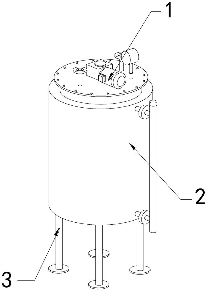
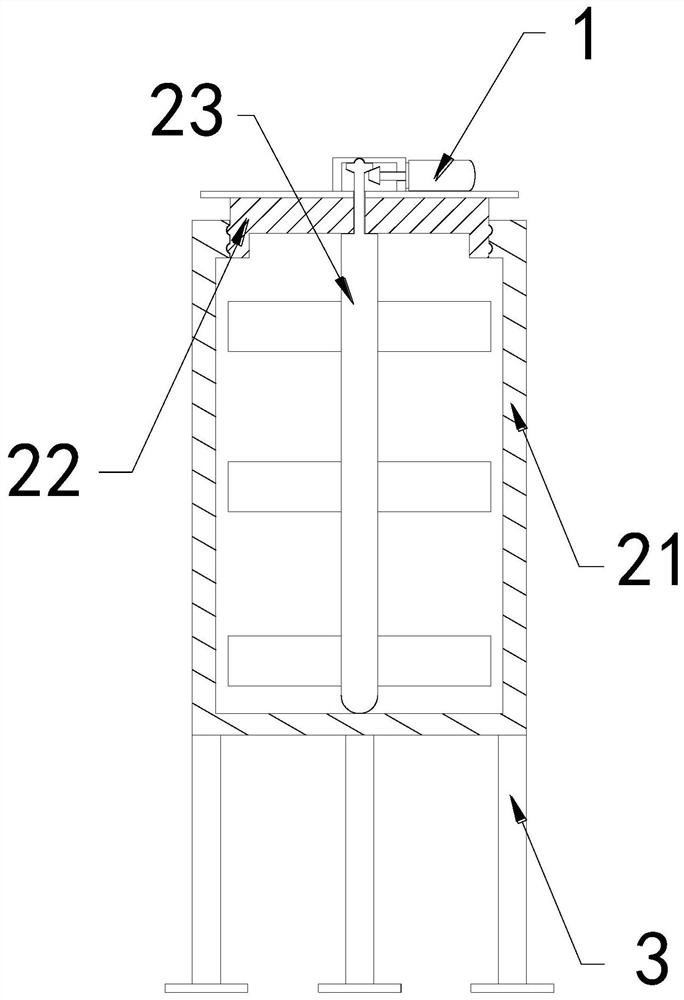
[0030] The invention provides an industrial enzyme fermentation device, the structure of which includes a driver 1, a fermenter 2, and a bracket 3, the driver 1 is installed on the top of the fermenter 2, and the bottom of the fermenter 2 is welded to the upper end of the bracket 3 The fermenter 2 includes an outer frame 21, a top cover 22, and a stirring paddle 23, the top cover 22 is screwed to the upper end of the inner wall of the outer frame 21, and the stirring paddle 23 runs through the top cover 22 internal position.

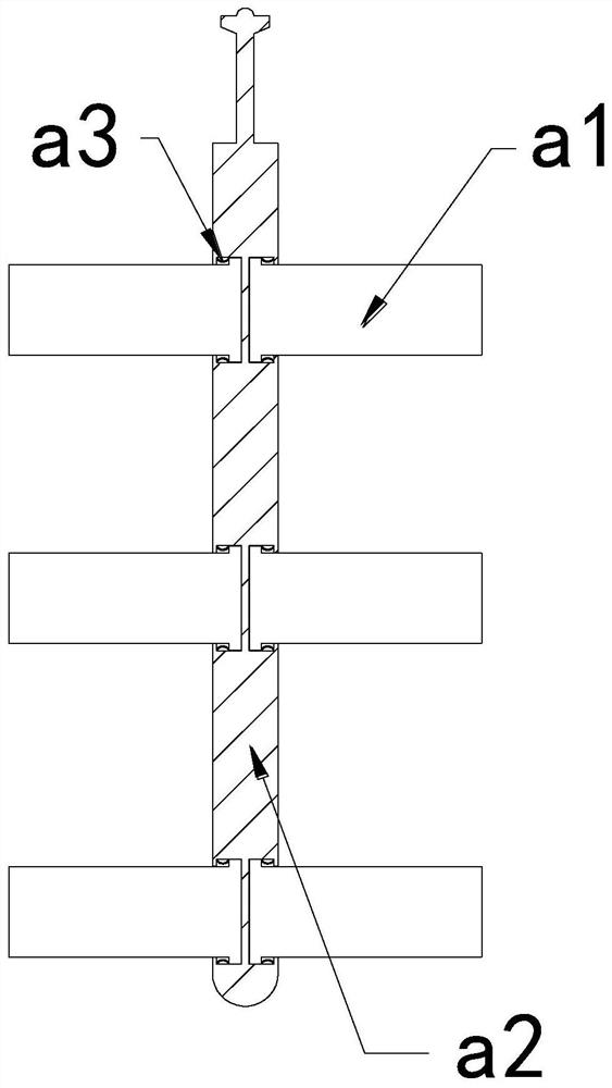
[0031] Wherein, the stirring paddle 23 includes a blade a1, a rotating shaft a2, and an elastic piece a3, the blade a1 is movably engaged with the inside of the rotating shaft a2, and the elastic piece a3 is installed between the inside of the rotating shaft a2 and the blade a1. There are six blades a1, and three are evenly distributed symmetrically on the left and right sides of the rotating shaf...

Embodiment 2

[0037] For example Figure 7 -example Figure 10 Shown:

[0038] Wherein, the middle solid plate b1 includes an upper push plate b11, a linkage rod b12, a bottom connecting plate b13, and an outer elastic piece b14, the bottom of the upper push plate b11 is attached to the top of the linkage rod b12, and the linkage rod b12 The side of the bottom connecting plate b13 is movably engaged with the inner wall of the bottom connecting plate b13. The outer elastic piece b14 is installed between the bottom of the upper push plate b11 and the upper surface of the bottom connecting plate b13. The mechanism shrinks to the extreme to generate vibration, which can make the push up The plate b11 moves up and down under the cooperation of the linkage rod b12 and the outer elastic piece b14, so that the hardened maltose attached to the upper surface of the upper push plate b11 can be vibrated to loosen.

[0039] Wherein, the push-up plate b11 includes a contact plate c1, a reset bar c2, a ba...


PUM


Abstract

The invention discloses an industrial enzyme fermentation device which structurally comprises a driver, a fermentation tank and a support, the driver is mounted at the top of the fermentation tank, the bottom of the fermentation tank is welded to the upper end of the support, and two outward extending blocks are pulled by a pull-back strip, so that the outward extending blocks can be rapidly contracted inwards along a plate body, a maltose layer attached to the surface of a leaf can be damaged in the contraction process, the damaged maltose layer on the outer surface of the leaf can fall off through vibration generated by contraction of an overhanging block to the maximum, and a sliding block can be downwards contracted and then separated from the bottom of a maltose block through inertia force generated by lifting of an upper push plate, the maltose blocks on the upper surface of a contact plate are impacted under the cooperation of a reset strip, and an outer sliding block is continuously pushed outwards through an outer pushing strip so that the outer sliding block can generate impact vibration on the inner wall of the contact plate, and the maltose blocks on the upper surface of the upper pushing plate can be quickly removed.

Description

technical field [0001] The invention relates to the technical field of high-efficiency industrial enzyme preparation, in particular to an industrial enzyme fermentation device. Background technique [0002] The industrial enzyme fermenter is mainly used for centralized fermentation of industrial enzymes and raw materials. By pouring the raw materials and industrial enzymes into the industrial enzyme fermenter, and then driving the mixer to stir the raw materials and industrial enzymes, the industrial Enzymes can ferment raw materials quickly and efficiently, and are widely used in food, textile, papermaking and other industries. Based on the above description, the inventors found that an existing industrial enzyme fermentation device mainly has the following deficiencies, such as: [0003] Because maltose is more viscous and will harden after cooling, if pectinase is fermenting maltose raw materials, it is easy for the maltose that is gradually fermented to adhere to the bla...

Claims


Application Information

Patent Timeline
Patent Type & Authority Applications(China)
IPC IPC(8): C12M1/40C12M1/02C12M1/00B08B7/02
CPCC12M21/18C12M23/38C12M23/48C12M27/02C12M39/00B08B7/02
Inventor 陈珍珍
Owner 陈珍珍
Learn More