Eureka AIR delivers breakthrough ideas for toughest innovation challenges, trusted by R&D personnel around the world.

Plate bending system and plate bending method

A technology of sheet metal and bending device, applied in the field of sheet metal bending, can solve the problems of no bending equipment and low work efficiency, and achieve the effect of improving the efficiency of automatic production

Active Publication Date: 2021-11-19
江苏德励达新材料股份有限公司
View PDF9 Cites 0 Cited by
  • Summary
  • Abstract
  • Description
  • Claims
  • Application Information

AI Technical Summary

Problems solved by technology

[0002] At present, there is no special bending equipment on the market, and bending is often performed by simple tooling or manually
[0003] However, the work efficiency of the above methods is not high, and the labor cost is far greater than the mechanical cost in the long run.

Method used


Image

  • Plate bending system and plate bending method
  • Plate bending system and plate bending method
  • Plate bending system and plate bending method

Examples


Embodiment 1

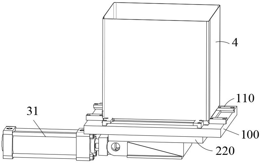
[0043] figure 1 is an exploded view of the plate bending system of the present invention;

[0044] figure 2 It is the overall assembly drawing of the plate bending system of the present invention.

[0045] In this example, if figure 1 , figure 2 As shown, this embodiment provides a plate bending system, which includes: a plate support frame 1, a plate bending device 2 and a driving device 3; wherein the plate bending device 2 is located on the inner ring of the plate support frame 1 The plate 4 is covered on the plate bending device 2, and the bottom of the plate 4 is placed on the plate supporting bracket 1, that is, the driving device 3 is suitable for driving the plate bending device 2 to the bottom four sides of the plate 4 Apply an outward thrust to make the four sides of the bottom of the plate 4 bend outward.

[0046] In this embodiment, the plate 4 is directly covered on the plate bending device 2, and at the same time, the bottom of the plate 4 is supported by ...

Embodiment 2

[0078] On the basis of Embodiment 1, this embodiment provides a sheet bending method, which includes: using the sheet bending system provided in Embodiment 1 to bend the sheet 4; by covering the sheet 4 on the sheet bending device 2, to place the bottom of the plate 4 on the plate supporting bracket 1; drive the plate bending device 2 through the driving device 3 to apply outward thrust to the bottom four sides of the plate 4, so that the bottom four sides of the plate 4 are folded outward bend.

[0079]To sum up, in the present invention, the plate is directly covered on the plate bending device, and at the same time, the bottom of the plate is supported by the plate supporting bracket, and the plate bending device is driven by the driving device to apply outward thrust to the four sides of the bottom of the plate. To achieve the function of bending the plate, it can improve the efficiency of automated production, and overcome the shortcomings of traditional simple tooling an...


PUM


Abstract

The invention belongs to the technical field of plate bending, and in particular relates to a plate bending system and a plate bending method. The plate bending system includes: a plate supporting bracket, a plate bending device and a driving device; wherein the plate bending device Located on the inner ring of the plate support bracket; the plate is covered on the plate bending device, and the bottom of the plate is placed on the plate support bracket, that is, the driving device is suitable for driving the plate bending device to the bottom four sides of the plate Apply an outward thrust to make the four sides of the bottom of the plate bend outwards; the present invention directly covers the plate on the plate bending device, and at the same time supports the bottom of the plate by the plate supporting bracket, and drives it through the driving device The plate bending device exerts outward thrust on the four sides of the bottom of the plate to realize the bending function of the plate, which can improve the efficiency of automatic production and overcome the shortcomings of traditional simple tooling and manual bending methods with low efficiency and high cost.

Description

technical field [0001] The invention belongs to the technical field of plate bending, and in particular relates to a plate bending system and a plate bending method. Background technique [0002] At present, there is no special bending equipment on the market, and bending is often performed by simple tooling or manually. [0003] However, the work efficiency of the above methods is not high, and the labor cost is far greater than the mechanical cost in the long run. [0004] Therefore, there is an urgent need to develop a new plate bending system and plate bending method to solve the above problems. Contents of the invention [0005] The object of the present invention is to provide a plate bending system and a plate bending method. [0006] In order to solve the above technical problems, the present invention provides a plate bending system, which includes: a plate supporting bracket, a plate bending device and a driving device; wherein the plate bending device is locat...

Claims


Application Information

Patent Timeline
Patent Type & Authority Patents(China)
IPC IPC(8): B21D19/08B21D43/00B29C65/74B29C65/78
CPCB21D19/082B21D43/003B29C65/74B29C65/7858B29C66/742
Inventor 奴坤顾斌
Owner 江苏德励达新材料股份有限公司
Why Eureka
Eureka Blog
Learn More