
Printed circuit board

A circuit board and current technology, which is applied to printed circuits, circuit devices, printed circuits, etc., can solve the problem of overheating of via holes and achieve the effect of improving overheating

Active Publication Date: 2021-09-17
WIWYNN CORP
View PDF10 Cites 0 Cited by
  • Summary
  • Abstract
  • Description
  • Claims
  • Application Information

AI Technical Summary

Problems solved by technology

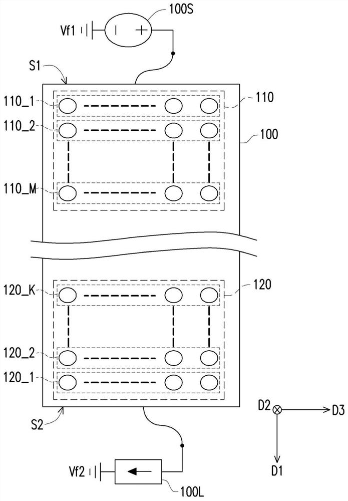
Generally speaking, among the plurality of via holes arranged in an array, a part of the via holes that are closer to the power supply unit or the load unit usually bears a higher amount of current, and this part of the via holes is prone to overheating. high case

Method used


Image

  • Printed circuit board
  • Printed circuit board
  • Printed circuit board

Examples


Embodiment Construction

[0040] In order to make the present invention may be more readily understood, a plurality of embodiments presented below to illustrate the present invention, however, the present invention is not limited to the illustrated embodiment a plurality of embodiments. And between Example embodiments also allow appropriate binding.

[0041] "Electrically connected (or coupled)" The term may refer to any direct or indirect connection means throughout this document (including the claims) used. For example, if a first device described herein is electrically connected (or coupled) to the second means should be interpreted as the first device may be directly connected to the second means, the first means or by other means may or some connecting means is indirectly coupled to the second means. The specification of the present disclosure (including claims) the reference to "first," "second," and the like terms are used to name the name element (element) or distinguish between different embodimen...


PUM


Abstract

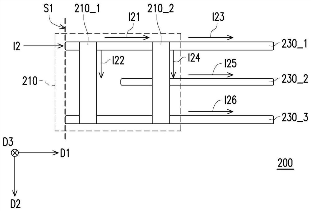
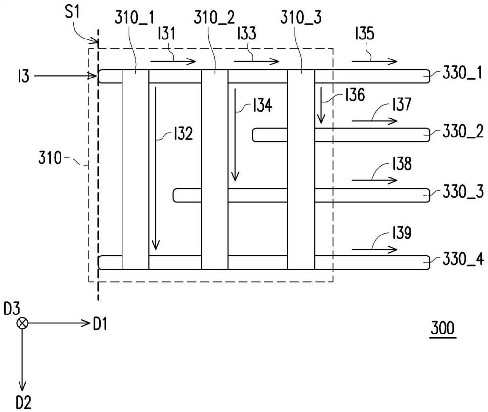
A printed circuit board is provided. The printed circuit board includes N power layers and a first via group. The N power layers are arranged in parallel and spaced from each other. The first via group includes M rows of vias which are disposed through the N power layers, where N and M are positive integers greater than 0. Each row of the M rows of vias is electrically connected to the first layer of the N power layers. A Pth row of the M rows of vias is further electrically connected to Q power layers of the N power layers respectively, wherein Q is the smallest positive integer greater than or equal to P((N-1) / M), and P is a positive integer less than or equal to M.

Description

Technical field [0001] The present invention relates to a power transmission element, and more particularly to a circuit board for providing power rail (power rail) is. Background technique [0002] Generally parallel to a multilayer circuit board and spaced from each other a power supply layer is formed, for example, and may include a plurality of vias (via) arranged in an array, wherein the vias may be electrically connected to the power supply unit or the load unit, to receive or transmit current. It is noted that each of the plurality of receiving a current amount of the via hole arranged in an array with electrically connected to the electrical power supply unit and the load unit or different. In general, the closer a portion of the via hole from the power supply unit or the load cell in the plurality of vias are arranged in an array typically withstand higher current, resulting in this portion of the via hole is too prone to temperature high. Therefore, how to design a spec...

Claims


Application Information

Patent Timeline
Patent Type & Authority Applications(China)
IPC IPC(8): H05K1/02H05K1/11
CPCH05K1/0203H05K1/115H05K2201/093H05K2201/09609H05K1/0265H05K2201/09309H05K3/429
Inventor 许成辅林政纬王丁凯
Owner WIWYNN CORP
Learn More