Closed air cooling tower process and system based on micro-interface hydrophilic filler

A cooling tower and interface technology, applied in the field of cooling towers, can solve the problems of high operating cost and energy consumption, achieve high popularization, improve mass transfer and heat transfer efficiency, and overcome high water consumption.

Inactive Publication Date: 2021-09-17
威海金宏科技有限公司
View PDF8 Cites 0 Cited by
  • Summary
  • Abstract
  • Description
  • Claims
  • Application Information

AI Technical Summary

Problems solved by technology

[0004] The purpose of this application is to provide a closed-circuit air cooling tower process and system based on micro-interface hydrophilic fillers, aiming to solve the technical problems of high operating costs and energy consumption in traditional closed-circuit cooling towers

Method used


Image

  • Closed air cooling tower process and system based on micro-interface hydrophilic filler
  • Closed air cooling tower process and system based on micro-interface hydrophilic filler
  • Closed air cooling tower process and system based on micro-interface hydrophilic filler

Examples


Embodiment 1

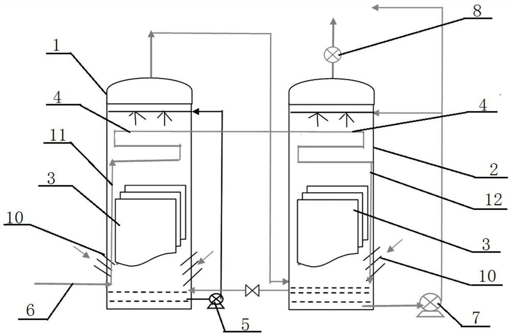
[0027] see figure 1 , a schematic flow diagram of a closed-type air cooling tower process based on micro-interface hydrophilic fillers provided by an embodiment of the present application. For the convenience of description, only the parts related to this embodiment are shown, and the details are as follows:

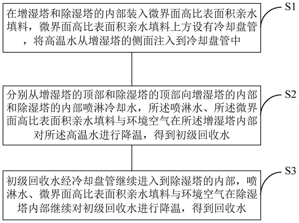
[0028] In one embodiment, the first aspect of the present application provides a closed-type air cooling tower process based on micro-interface hydrophilic fillers for cooling high-temperature water, including the following steps:

[0029] S1. Install micro-interface high specific surface area hydrophilic packing inside the humidification tower and dehumidification tower, and install a cooling coil above the micro-interface high specific surface area hydrophilic packing, and inject high-temperature water from the side of the humidification tower into the cooling plate tube.

[0030] Specifically, both the humidification tower and the dehumidification tower are made of c...

Embodiment 2

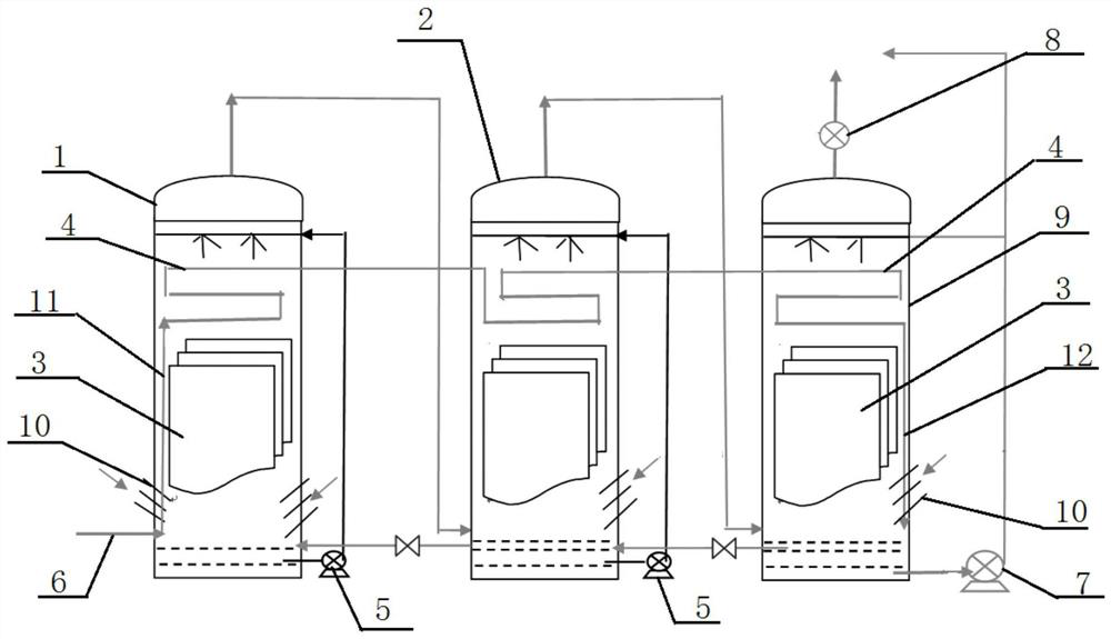
[0040] The rest are the same as in Example 1, the difference is that there are at least two dehumidification towers, the primary recovered water is cooled by at least two dehumidification towers to obtain recovered water, the cooling coils in each tower are connected, and the outlet pipes are installed in Inside the last stage of dehumidification tower, the primary recycled water is cooled step by step through each dehumidification tower until the temperature of the recycled water drops to 20-22°C, and then pumped into the cooling water storage tank for recycling. The dehumidified environment inside the dehumidification tower The air is discharged into the atmosphere through the induced draft fan at the top of the last stage dehumidification tower.

[0041] The temperature of the high temperature water to be cooled is 50-60°C, and the flow rate is 210m 3 / h, in order to prevent fouling, the linear velocity of high-temperature water in the cooling coil is designed to be 0.8-1.0...


PUM

PropertyMeasurementUnit
densityaaaaaaaaaa
voidageaaaaaaaaaa
voidageaaaaaaaaaa

Abstract

The invention discloses a closed air cooling tower process and system based on a micro-interface hydrophilic filler .The closed air cooling tower process and system based on the micro-interface hydrophilic filler comprises the following steps that a micro-interface high-specific-surface-area hydrophilic filler is arranged in a humidifying tower and a dehumidifying tower, a cooling coil is arranged above the micro-interface high-specific-surface-area hydrophilic filler, and high-temperature water is injected into the cooling coil from the side face of the humidifying tower; cooling water is sprayed to the interior of the humidifying tower and the interior of the dehumidifying tower from the top of the humidifying tower and the top of the dehumidifying tower respectively, the high-temperature water is cooled by the spraying water, the micro-interface high-specific-surface-area hydrophilic filler and ambient air in the humidifying tower, and primary recycled water is obtained; the primary recycled water continues to enter the dehumidifying tower through the cooling coil, the spraying water, the micro-interface high-specific-surface-area hydrophilic filler and ambient air continue to cool the primary recycled water in the dehumidifying tower, recycled water is obtained, and the technical problems that a traditional closed cooling tower is high in operation cost and energy consumption are solved. The invention belongs to the technical field of cooling towers.

Description

technical field [0001] The present application relates to the technical field of cooling towers, in particular to a closed-type air cooling tower process and system based on micro-interface hydrophilic fillers. Background technique [0002] Cooling towers are needed in the fields of chemical industry, food, medicine, energy, metallurgy, further processing, material handling and processing. At present, open cooling towers and closed cooling towers are mostly used in China. The open cooling tower sprays hot water onto the glass fiber filler in the form of spray, and achieves heat exchange and cooling through the contact between water and air. A fan is installed on the top to drive the flow of air in the tower, and the heat exchanged with water The hot air flow is brought out to achieve cooling. This cooling method has low investment and mature technology, but the operating costs such as water consumption and power consumption are high. At the same time, the open cooling tower ...

Claims


Application Information

Patent Timeline
Patent Type & Authority Applications(China)
IPC IPC(8): F28C1/14F28F25/08F28F25/04F28F25/10
CPCF28C1/14F28F25/08F28F25/04F28F25/10
Inventor 刘昌豹李栋李春虎
Owner 威海金宏科技有限公司
Why Eureka
Try Eureka