Novel gas-liquid separate production pipe column for underground drainage gas production of sulfur-containing gas well

A completion string, gas-liquid technology, applied in wellbore/well components, drill pipe, casing, etc., can solve problems such as hidden safety hazards, unsuitable for sulfur-containing gas wells, and no consideration of casing protection, etc., to avoid damage Effect

Inactive Publication Date: 2021-09-17
SOUTHWEST PETROLEUM UNIV
View PDF16 Cites 1 Cited by
  • Summary
  • Abstract
  • Description
  • Claims
  • Application Information

AI Technical Summary

Problems solved by technology

[0006] The key to realizing gas-liquid separation is how to establish a gas-liquid separation channel. The predecessors proposed a variety of gas-liquid separation string structures, such as: patent CN110593846A discloses a gas-liquid separation system for offshore gas well drainage and gas recovery Production string, this process string uses the oil casing annulus to drain liquid after separating gas and liquid downhole, which is contrary to the concept of casing protection in sour gas wells, and has great potential safety hazards, so this process string is not Applicable to sulfur-containing gas wells; patent CN104047588A proposes a downhole gas-liquid separation string suitable for pumping wells, but this process also does not consider the protection of casing; patents CN2758474Y and CN201763310U also propose downhole gas-liquid separation strings, but these strings are not suitable for sour gas wells due to the wellbore structure and lack of casing protection

Method used


Image

  • Novel gas-liquid separate production pipe column for underground drainage gas production of sulfur-containing gas well

Examples


Embodiment Construction

[0013] By the following specific examples to embodiments of the present invention is further illustrated done:

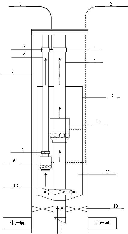
[0014] Append figure 1 It is shown, which can be used downhole sour gas-liquid drainage gas partial mining new column, which comprises a sleeve 6, the bottom of the cans into the sleeve 6 ESP system 8, vertically disposed sleeve 6 liquid discharge pipe 5 and the gas inside the tubing 4, the liquid 5 and gas discharge pipe 4 are mounted on the tubing downhole safety valve 3, valve 3 is connected to the ground equipment via a control line; canned submersible electric 8 pump system includes a gas-liquid separator 10, the ESP 10, ESP 9 and its accompanying components such as the automatic valve 7, and 9 of the electric submersible pump 10 through the ESP cable 2 and ground equipment connected.

[0015] Present invention provides a liquid drainage gas downhole sour gas for new methods and workflow sub-string is taken:

[0016] This downhole gas-liquid separator taken from th...


PUM


Abstract

The invention provides a novel gas-liquid separate production pipe column for underground drainage gas production of a sulfur-containing gas well. The novel gas-liquid separate production pipe column comprises a casing pipe, a canned electric submersible pump system arranged at the bottom of the casing pipe, a gas production oil pipe and a liquid discharge oil pipe, the gas production oil pipe and the liquid discharge oil pipe are vertically arranged in the casing pipe, underground safety valves are further mounted on the gas production oil pipe and the liquid discharge oil pipe, and the underground safety valves are connected with ground equipment through control pipelines; and the canned electric submersible pump system mainly comprises two electric submersible pumps, automatic reversing valves and a gas-liquid separator, wherein the automatic reversing valves are respectively matched with the two electric submersible pumps, and the two electric submersible pumps are connected with the ground equipment through cables. According to the novel gas-liquid separate production pipe column, corrosive fluid is not in contact with the casing pipe all the time, so that the concept of protecting the casing pipe for the sulfur-containing gas well is met; and in addition, the canned electric submersible pump system is used for achieving underground gas-liquid separate production, damage to the electric submersible pumps caused by gas-liquid simultaneous production is avoided, and the novel gas-liquid separate production pipe column is excellent in effect and has very high use benefits.

Description

Technical field [0001] The present invention relates to the field of oil and gas exploration wells Drainage technology, particularly relates to a method for liquid drainage gas downhole sour gas mining new partial string. Background technique [0002] In the mining process gas wells, gas wells when the flow rate is below the critical liquid carrying gas flow rate, gas well began effusion, gas well bore fluid will severely limit the productivity of gas wells, gas wells will lead to severe flooding discontinued. Gas drainage process is an effective way to solve the problem of gas well fluid. [0003] At present, a process for mainly liquid discharge gas well gas lift bubble discharge, the plunger lift and ESP, etc. Generally, these liquid discharge gas production process to meet the needs of the drainage wells under different conditions, but the special sour gas well structure, most of the process is not applicable to sour gas wells, especially large amount of liquid sour gas stron...

Claims


Application Information

Patent Timeline
Patent Type & Authority Applications(China)
IPC IPC(8): E21B43/00E21B17/00E21B43/38
CPCE21B43/00E21B17/00E21B43/38
Inventor 王志彬梁道远凌金权郑传根
Owner SOUTHWEST PETROLEUM UNIV
Why Eureka
Try Eureka