
Electric vehicle charging system and charging method based on intelligent fusion terminal

A charging method and electric vehicle technology, applied in electric vehicle charging technology, electric vehicles, efficient vehicle charging, etc., can solve problems such as aggravated distribution network load pressure, long transformation time, load peak superposition, etc., to achieve orderly charging Reliable, reliable and orderly charging, and easy operation

Active Publication Date: 2022-08-02
STATE GRID HUNAN ELECTRIC POWER +2
View PDF9 Cites 0 Cited by
  • Summary
  • Abstract
  • Description
  • Claims
  • Application Information

AI Technical Summary

Problems solved by technology

[0002] At present, the demand for charging in residential areas continues to grow, and the power distribution network is under greater pressure. Most users will basically charge their electric vehicles after returning home. This will roughly coincide with the peak period of electricity load and charging time, resulting in load peaks. The further superposition of the distribution network intensifies the load pressure and threatens the safety and reliability of power supply in the station area.
Large-scale disorderly charging will bring huge challenges to the safe, economical and reliable operation of the power grid. It is difficult for the existing distribution network to meet the requirements of disorderly charging in residential areas. If the distribution network is transformed, the investment will be huge and the transformation time will be long

Method used


Image

  • Electric vehicle charging system and charging method based on intelligent fusion terminal
  • Electric vehicle charging system and charging method based on intelligent fusion terminal
  • Electric vehicle charging system and charging method based on intelligent fusion terminal

Examples


Embodiment Construction

[0027] The present invention will be further described below with reference to the accompanying drawings and specific embodiments.

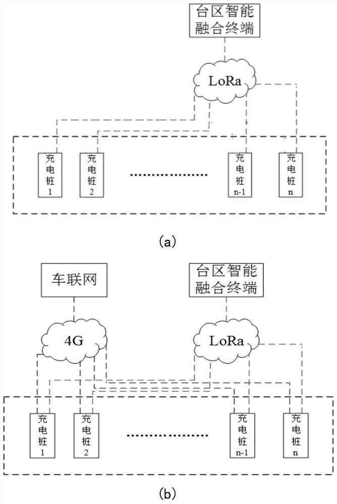
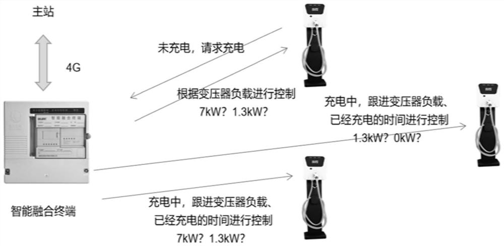
[0028] like figure 1 and figure 2 As shown in the figure, the electric vehicle charging system based on the intelligent fusion terminal in this embodiment includes an intelligent fusion terminal, an orderly charging communication unit, an AC charging pile, an intelligent circuit breaker, a power distribution box, etc.; The charging communication units are respectively equipped with LoRa communication modules; the AC charging pile communicates with the Internet of Vehicles through 4G, and communicates with the intelligent fusion terminal in the station area through the micro-power LoRa method; the intelligent fusion terminal is used to collect the total load of the distribution transformer and the charging power of each charging pile. , and according to the total load of the distribution transformer and the charging power of each charging pile, ...


PUM


Abstract

The invention discloses an electric vehicle charging system and method based on an intelligent fusion terminal. The system includes an intelligent fusion terminal and a plurality of charging piles, and the intelligent fusion terminal is connected with each charging pile; the intelligent fusion terminal is used to collect the total load of the distribution transformer and The charging power of each charging pile, and according to the total load of the distribution transformer and the charging power of each charging pile, the orderly charging control of each charging pile is carried out. The method includes: collecting the total load of the distribution transformer and the charging power of each charging pile in real time; when the residual power of the distribution is greater than the first residual power limit, charging directly; when the residual power is less than the second residual power limit, charging The charging power of the charged charging pile is lowered, and the newly connected charging pile is charged at high power; when the remaining power is less than the third remaining power limit, the charging power of an already charged charging pile is lowered again, and the newly connected charging pile is charged with high power; The incoming charging pile is charged at low power. The invention has the advantages of simple operation, low cost, reliable and orderly charging and the like.

Description

technical field [0001] The invention mainly relates to the technical field of electric vehicle charging, in particular to an electric vehicle charging system and a charging method based on an intelligent fusion terminal. Background technique [0002] At present, the demand for charging in residential areas is increasing, and the power distribution network is under great pressure. Most users will basically charge their electric vehicles after returning home, which will make the peak period of the electricity load roughly coincide with the charging time, resulting in a peak load. The further superposition of the power distribution network aggravates the load pressure of the distribution network and threatens the safety and reliability of the power supply in the Taiwan area. Large-scale disordered charging will bring huge challenges to the safe, economical and reliable operation of the power grid. It is difficult for the existing distribution network to carry the disordered cha...

Claims


Application Information

Patent Timeline
Patent Type & Authority Patents(China)
IPC IPC(8): B60L53/67B60L53/63B60L53/62B60L53/68
CPCB60L53/67B60L53/63B60L53/62B60L53/68Y02T90/16Y02T10/92
Inventor 邓威罗威成唐海国朱吉然刘奕游金梁康童周可慧
Owner STATE GRID HUNAN ELECTRIC POWER
Learn More