
Automatic plastic spraying system for guardrails

A guardrail and plastic spraying technology, applied in the direction of injection devices, injection devices, liquid injection devices, etc., can solve the problems of limited use environment, excessive waste, and large odor, and achieve the effects of wide application range, waste reduction, and injury reduction

Inactive Publication Date: 2021-09-17
厦门互知科技有限公司
View PDF0 Cites 0 Cited by
  • Summary
  • Abstract
  • Description
  • Claims
  • Application Information

AI Technical Summary

Problems solved by technology

[0002] At present, the guardrails are all sprayed before installation, and there is more manual participation, or the machine occupies a large area, the spray powder is wasted more, the manual spray is uneven, the efficiency is slow, the waste is also large, and the smell is relatively large , and most of the plastic spraying in factories is spraying color in large quantities. The spraying of guardrails with complex shapes is not uniform and needs to be painted multiple times, and the spraying is more artificially controlled, writing programs, etc., requiring more professional people Participation, for outdoor guardrails with peeling paint, only manual spraying is required, the use environment of the factory spraying machine is limited, and it is inconvenient to move

Method used


Image

  • Automatic plastic spraying system for guardrails
  • Automatic plastic spraying system for guardrails
  • Automatic plastic spraying system for guardrails

Examples


Embodiment Construction

[0017] In order to make the purpose and advantages of the present invention clearer, the present invention will be described in detail below in conjunction with the examples. It should be understood that the following words are only used to describe a guardrail automatic spray molding system or several specific implementations of the present invention, and Without strictly limiting the scope of protection specifically claimed by the present invention, as used herein, the terms up, down, and left and right are not limited to their strict geometric definitions, but include reasonable and inconsistent tolerances for machining or human error, as detailed below Describe the specific features of this guardrail automation spray system:

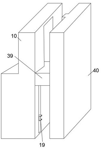
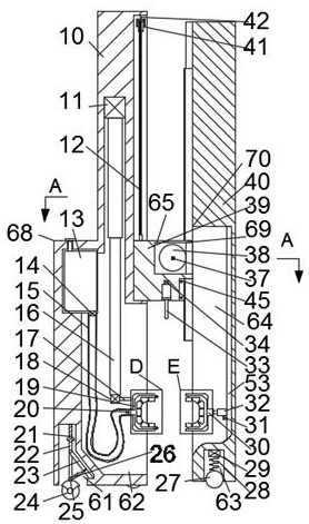
[0018] refer to Figure 1-8 According to an embodiment of the present invention, a guardrail automation spray system includes a casing 10, a second casing 39 of a sliding block, and a third casing 40 of a measuring block. The casing 10 is provided wi...


PUM


Abstract

The invention discloses an automatic plastic spraying system for guardrails. The automatic plastic spraying system for the guardrails comprises a machine shell, a second sliding block machine shell and a third measuring block machine shell, wherein four moving cavities with the lower ends communicating with the outside are formed in the machine shell; control cavities with the right ends communicating with the outside are formed in the upper end walls of the moving cavities; a rope winding cavity is formed in the machine shell; a driving cavity is formed in the second machine shell; a detection cavity with the lower section communicating with the outside is formed in the third measuring block machine shell; an execution cavity with the left end communicating with the outside is formed in the upper end wall of the detection cavity; two symmetrical driven cavities are formed in the front part and the rear part of the interior of a driven plastic spraying ring and the front part and the rear part of the interior of a driving plastic spraying ring respectively; an automatic spring is fixedly connected with a sealing ball; the sealing ball is opened when the liquid pressure intensity is increased, so that paint can pass through; the lower end face of the second machine shell is slidably connected with a detection rod; the detection rod can detect the height of a guardrail; a measurement ball is arranged in a detection cavity; and the measurement ball can control stopping of the third machine shell, so that the third machine shell is prevented from colliding with the ground.

Description

technical field [0001] The invention relates to the technical field of construction engineering, in particular to an automatic plastic spraying system for guardrails. Background technique [0002] At present, the guardrails are all sprayed before installation, and there is more manual participation, or the machine occupies a large area, the spray powder is wasted more, the manual spray is uneven, the efficiency is slow, the waste is also large, and the smell is relatively large , and most of the plastic spraying in factories is spraying color in large quantities. The spraying of guardrails with complex shapes is not uniform and needs to be painted multiple times, and the spraying is more artificially controlled, writing programs, etc., requiring more professional people Participation, for outdoor guardrails with peeling paint, it can only be manually sprayed, and the use environment of the factory spraying machine is limited, and it is inconvenient to move. Contents of the...

Claims


Application Information

Patent Timeline
IPC IPC(8): B05B9/04B05B15/628B05B13/04B05B1/02B05B12/12
CPCB05B9/0409B05B15/628B05B13/041B05B1/02B05B12/124
Inventor 王文
Owner 厦门互知科技有限公司
Learn More