Urine collecting device for neonatal nursing
A collection device and technology for neonates, applied in the field of medical supplies, can solve the problems of difficult to control collection time, urine falling on the ground or even on the bed, and neonatal urination is very random.
- Summary
- Abstract
- Description
- Claims
- Application Information
AI Technical Summary
Problems solved by technology
Method used
Image
Examples
Embodiment 1
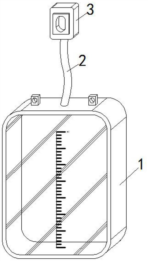
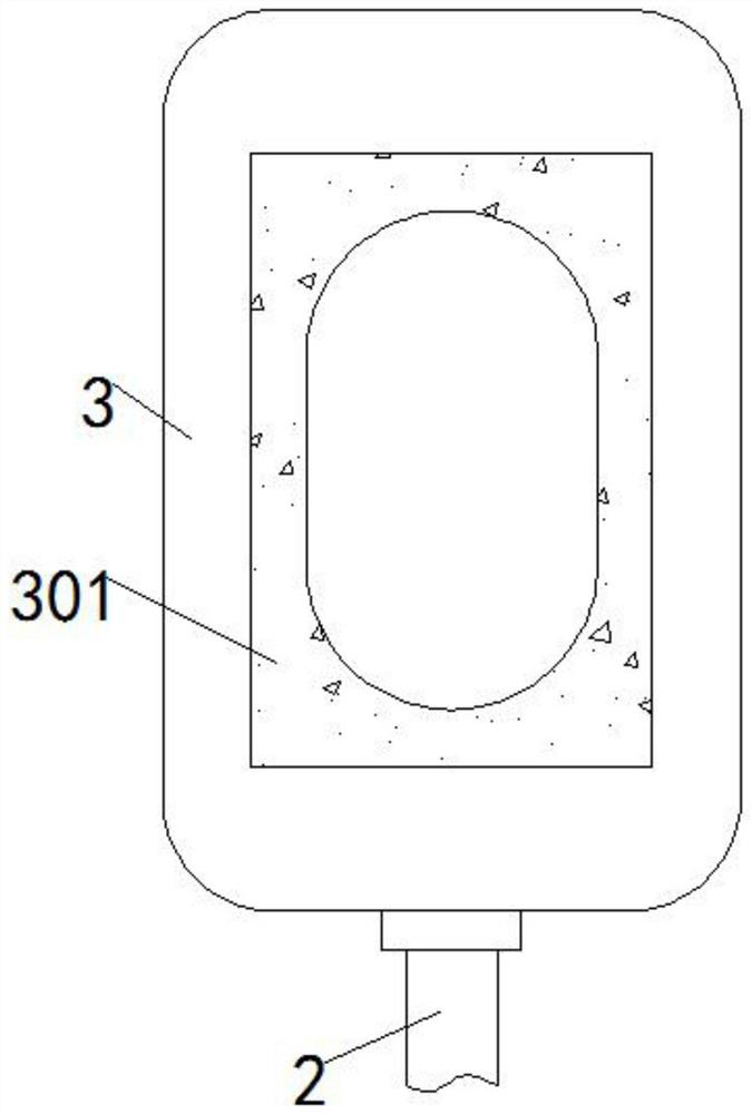
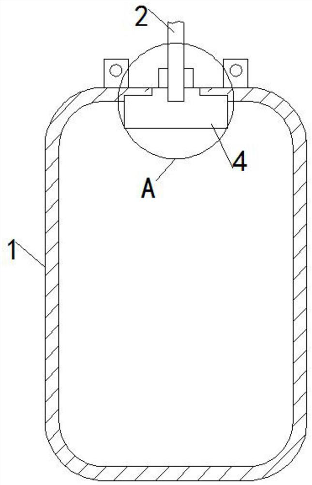
[0025] see Figure 1-4 , in an embodiment of the present invention, a urine collection device for neonatal care includes a urine receiving bag 1, a catheter 2, a connecting bag 3 and a sealing mechanism 4 to prevent urine from overflowing, the top of the urine receiving bag 1 is embedded with a catheter 2, The top of the catheter 2 is nested with a connection bag 3, and the back of the connection bag 3 is embedded with a foam sticker 301 with a middle opening. The inner top of the urine bag 1 is fixedly connected with a sealing mechanism 4, and the sealing mechanism 4 is connected to the bottom of the catheter 2. , and the center of the bottom of the sealing mechanism 4 is provided with a rectangular opening with a small top and a large bottom to communicate with the bottom of the catheter 2. The sealing mechanism 4 is embedded with a first airbag 401, and the first airbag 401 is arranged in a surrounding shape relative to the rectangular opening, and the second The bottom of ...
Embodiment 2
[0029] see Figure 4 and Figure 5 , in this embodiment, including a locking mechanism 5 to prevent urine from falling, the outer surface of the bottom of the catheter 2 is nested with a locking mechanism 5, and the inner wall of the joint between the catheter 2 and the locking mechanism 5 is embedded with an expansion surface 201, and the expansion surface The middle end of 201 is embedded with a buffer airbag 202, the top of the locking mechanism 5 is slidingly provided with a push rod 501, and the bottom of the push rod 501 is fixedly connected with a lower push plate 503, and the joint between the top of the locking mechanism 5 and the push rod 501 is installed with a snap lock There is a stopper 502, and the surface of the push rod 501 is provided with a groove to cooperate with the positioning locker 502. A connecting rod 504 is slid inside the locking mechanism 5, and the left end of the connecting rod 504 is attached to the expansion surface 201. The connecting rod Th...
Embodiment 3
[0032] see Figure 4 , Image 6 and Figure 7 The leftmost side of the sealing block 403 is embedded with a second airbag 4031, and the second airbag 4031 communicates with the interior of the sealing block 403, and the surface of the second airbag 4031 is provided with an inflatable raised small airbag, and the inside of the sealing block 403 is embedded A sliding sleeve 4034 is provided, and a flexible rod 4033 is slidably arranged inside the sliding sleeve 4034. The bottom and the right side of the sealing block 403 are movably connected with a baffle plate 4032 through a spring shaft, and the two baffle plates 4032 are connected to the two ends of the flexible rod 4033 respectively. connected.
[0033]In this embodiment, when the sealing block 403 is pushed out under pressure, the baffle plate 4032 at the bottom of the sealing block 403 loses the friction binding force of the sealing mechanism 4 and expands downward under the action of the spring shaft, so that the air i...
PUM
 Abstract
Description
Claims
Application Information
 - R&D Engineer
- R&D Manager
- IP Professional
- Industry Leading Data Capabilities
- Powerful AI technology
- Patent DNA Extraction
Browse by: Latest US Patents, China's latest patents, Technical Efficacy Thesaurus, Application Domain, Technology Topic, Popular Technical Reports.
© 2024 PatSnap. All rights reserved.Legal|Privacy policy|Modern Slavery Act Transparency Statement|Sitemap|About US| Contact US: help@patsnap.com


