Abdominal color Doppler ultrasound image display equipment
A technology for image display and display equipment, applied in the field of image display equipment, can solve the problems of inconvenient storage, inconvenient display, and angle adjustment, and achieve the effect of easy display and easy storage.
- Summary
- Abstract
- Description
- Claims
- Application Information
AI Technical Summary
Problems solved by technology
Method used
Image
Examples
Embodiment 1
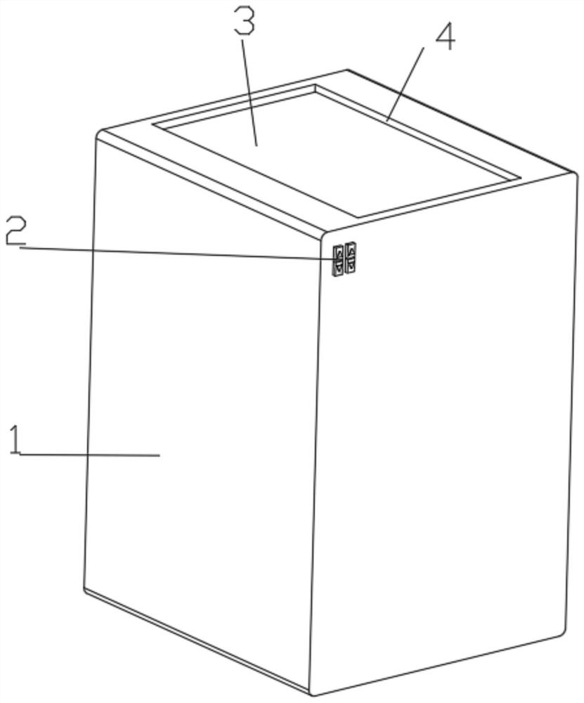
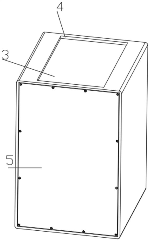
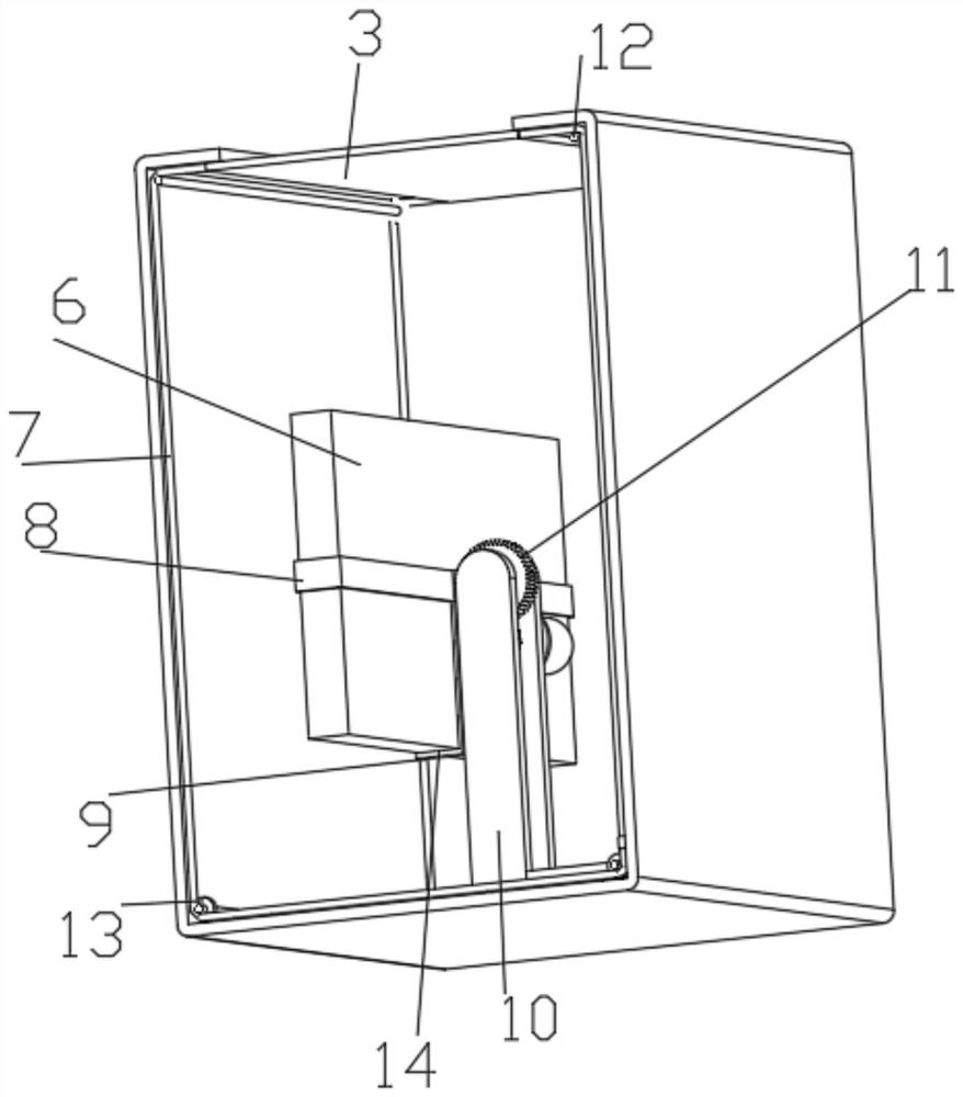
[0037] Such as figure 1 , 2 , 3, 4, 5, and 6 show an abdominal color ultrasound image display device, including an installation box 1 and a display device 6, the top of the installation box 1 is provided with a straight hole 4, and the display device 6 moves up and down in the straight hole 4 , the inner bottom of the installation box 1 is connected with a position adjustment structure for height adjustment of the display device 6, the position adjustment structure includes a U-shaped plate 10, a slide plate 15, a first bevel gear 17, a first drive motor 19, a threaded rod 20, a support Guide rod 21 and the second bevel gear 22, the first drive motor 19 and the support guide rod 21 are all fixedly installed on the inner bottom of the installation box 1, the output shaft of the first drive motor 19 is fixedly connected with the second bevel gear 22, installed The inner bottom of the box 1 is rotatably connected with a threaded rod 20 through a fixedly connected bearing, the lo...
Embodiment 2
[0040] Embodiment 2 is a further improvement to Embodiment 1.
[0041] Such as image 3 , 5 , 6, and 7, the U-shaped plate 10 is connected with an angle adjustment structure for the angle adjustment of the display device 6, and the angle adjustment structure includes a first ring gear 11, a second drive motor 23, a rotating shaft 24 and a second ring gear 25, The upper inner wall of the inner wall of the U-shaped plate 10 is sequentially connected with the first ring gear 11 and the rotating shaft 24 through fixedly connected bearings from top to bottom, and the second ring gear 25 is fixedly installed on the rotating shaft 24, and the second ring gear 25 The top of the U-shaped plate is meshed with the bottom of the first ring gear 11, and the outer wall of the U-shaped plate 10 is fixedly connected with a second drive motor 23. The output end of the second drive motor 23 penetrates the U-shaped plate 10 and is fixedly connected with the rotating shaft 24. The side wall of ...
Embodiment 3
[0043] Embodiment 3 is a further improvement to Embodiment 1.
[0044] Such as image 3 , 4 As shown, the first ring gear 11 is connected with a mounting structure for the installation of the display device 6. The mounting structure includes a horizontal plate 8, a straight plate 9, a straight groove 14 and a convex groove 26, and the top of the straight plate 9 is fixedly installed on the bottom of the horizontal plate 8. At the middle end, the bottom of the straight plate 9 is provided with a straight groove 14, and the side wall of the horizontal plate 8 is provided with a convex groove 26. The bottom plate of the display device 6 is inserted in the straight groove 14, and the side wall of the display device 6 and the convex groove 26 The inner wall of the display device 6 is inserted into the convex groove 26 of the horizontal plate 8 of the installation structure, and then the bottom plate of the display device 6 is inserted in the straight groove 14 of the straight plat...
PUM
 Abstract
Description
Claims
Application Information
 - Generate Ideas
- Intellectual Property
- Life Sciences
- Materials
- Tech Scout
- Unparalleled Data Quality
- Higher Quality Content
- 60% Fewer Hallucinations
Browse by: Latest US Patents, China's latest patents, Technical Efficacy Thesaurus, Application Domain, Technology Topic, Popular Technical Reports.
© 2025 PatSnap. All rights reserved.Legal|Privacy policy|Modern Slavery Act Transparency Statement|Sitemap|About US| Contact US: help@patsnap.com


