
Radial magnetic pole damping cage structure of generator rotor

A generator rotor and rotor magnetic pole technology, applied in the direction of magnetic circuit shape/style/structure, winding conductor shape/style/structure, electrical components, etc., can solve high production cost, complex processing technology, production technology and installation work ask advanced questions

Pending Publication Date: 2021-09-14
安徽德科电气科技有限公司
View PDF0 Cites 0 Cited by
  • Summary
  • Abstract
  • Description
  • Claims
  • Application Information

AI Technical Summary

Problems solved by technology

That is to say, the stator and rotor slots of the generator are set as inclined slots, that is, the slots on each stator and rotor punch are superimposed to form an inclined winding slot, and there is a gap between the winding slot and the winding. This weakens the high-order The stator and rotor structure of electromagnetic harmonics has high requirements for the production process and installation work of stator and rotor punching, the processing technology is complicated, the yield rate is low, and the production cost is high

Method used


Image

  • Radial magnetic pole damping cage structure of generator rotor
  • Radial magnetic pole damping cage structure of generator rotor
  • Radial magnetic pole damping cage structure of generator rotor

Examples


Embodiment Construction

[0016] In order to facilitate those skilled in the art to understand the technical solution of the present invention, the technical solution of the present invention will be further described in conjunction with the accompanying drawings.

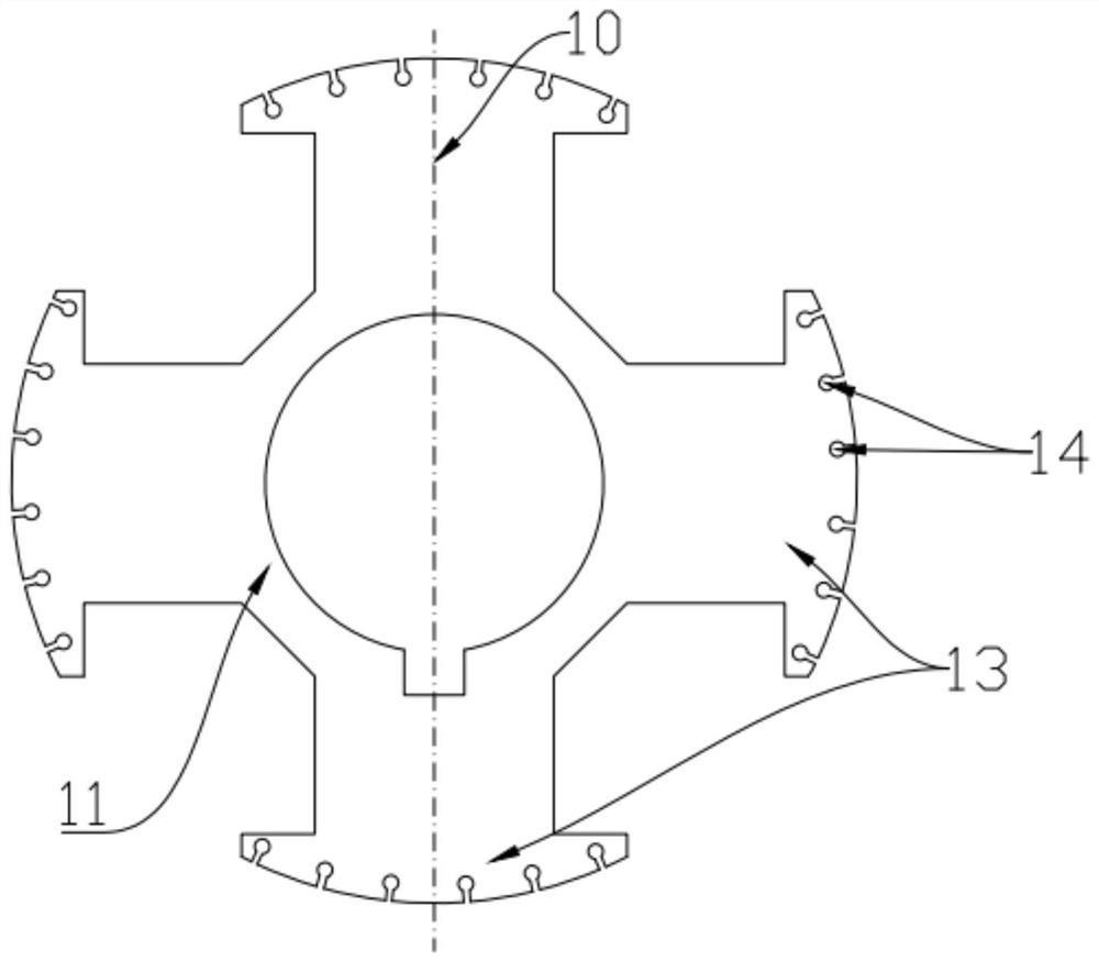
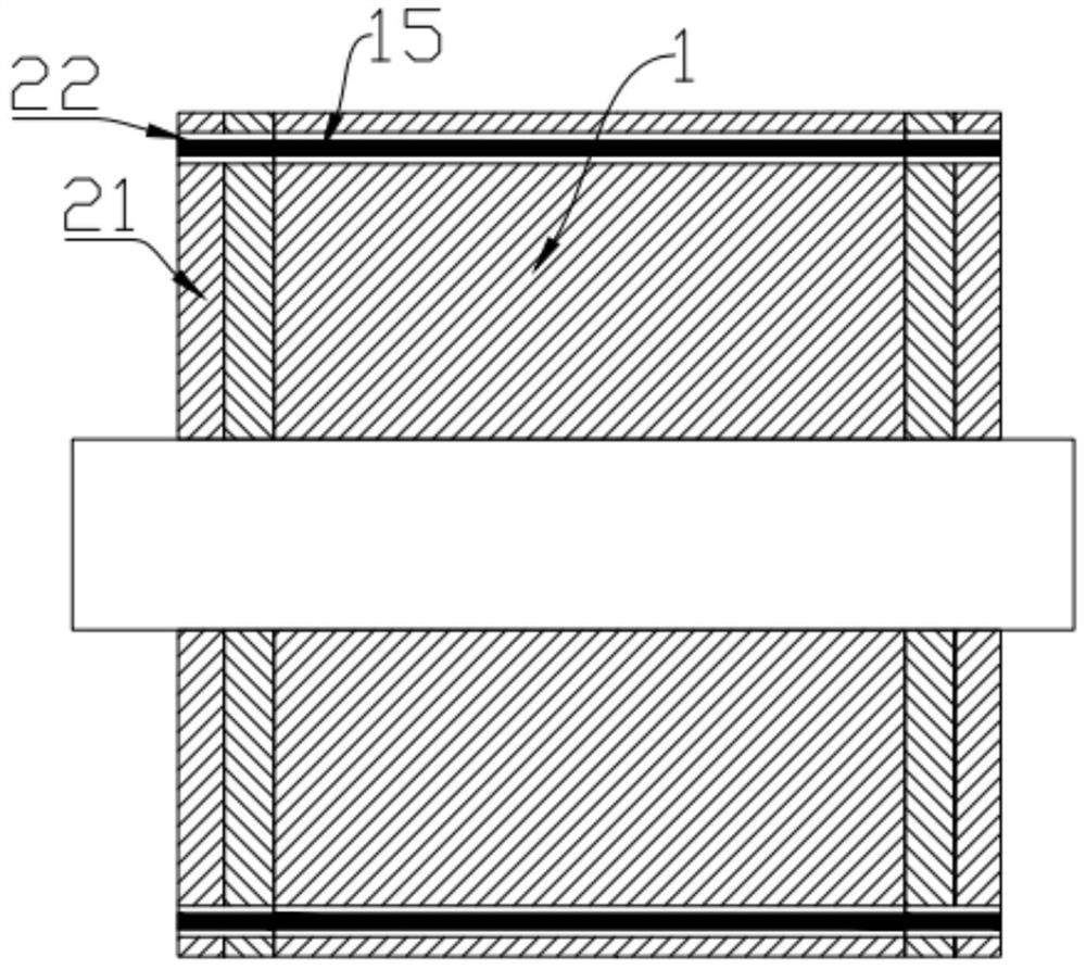
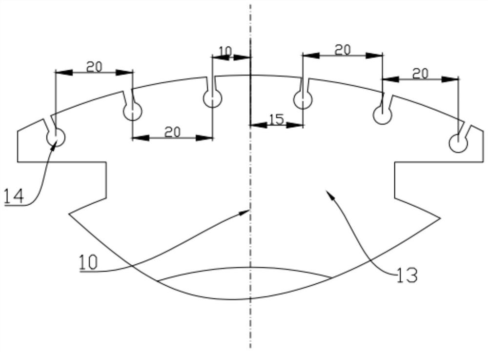
[0017] Such as figure 1 and figure 2 As shown, the technical solution of the present invention is a generator rotor radial pole damping cage structure, including two damping rings 21 placed at both ends of the rotor 1 and several damping rings 21 that pass through the rotor core 1 and are electrically connected to the two damping rings 21. Guide bar 15. The rotor 1 includes a rotor core 11 , a rotor pole 13 and several damping holes 14 arranged on the rotor pole 13 . The damping hole 14 is a straight slot damping hole whose central axis is parallel to the axis of the rotor core 1 . The damping holes 14 on the same rotor pole 13 are arranged at asymmetric intervals, that is, the pitches of the damping holes (the distance between two adja...


PUM


Abstract

The invention discloses a radial magnetic pole damping cage structure of a generator rotor, which comprises two damping rings arranged at the two ends of a rotor respectively and a plurality of damping guide bars penetrating through a rotor core and electrically connected with the two damping rings, and the rotor comprises the rotor core, a rotor magnetic pole and a plurality of damping holes formed in the rotor magnetic pole. The damping holes are straight groove damping holes with the central axes parallel to the axis of the rotor iron core, the damping holes in the rotor magnetic poles are asymmetrically arranged at intervals, the distribution circle radiuses of all the damping holes are equal, the damping holes in the adjacent rotor magnetic poles are symmetrically arranged, and the same rotor magnetic pole has at least two sizes of damping hole pitches. According to the radial magnetic pole damping cage structure of the generator rotor, the amplitude of current harmonic waves in the damping winding can be effectively suppressed, the voltage waveform distortion rate is reduced, high-quality electric energy is obtained, and electromagnetic noise generated by the harmonic waves is weakened.

Description

technical field [0001] The invention belongs to the field of generators, and more specifically relates to a generator rotor radial magnetic pole damping cage structure. Background technique [0002] In the prior art, in the harmonic suppression means of synchronous generators, the main methods are: 1. Reasonably increase the impedance of the stator and rotor windings. 2. Install a damping winding on the rotor. 3. In terms of winding structure and parameter improvement, short-distance windings and hybrid windings can reduce harmonic interference. 4. The non-sinusoidal distribution of the air gap magnetic field can be reduced by improving the design of the magnetic poles of the stator and rotor magnetic slot wedges, chute and slot modification. Among the above-mentioned four harmonic suppression methods, the stator-rotor inclined slot method is the most commonly used in the prior art. That is to say, the stator and rotor slots of the generator are set as inclined slots, tha...

Claims


Application Information

Patent Timeline
Patent Type & Authority Applications(China)
IPC IPC(8): H02K3/20H02K1/24
CPCH02K3/20H02K1/24H02K2213/03
Inventor 石斌邬向东张庆玉吴红龚羊飞
Owner 安徽德科电气科技有限公司
Learn More