Loop type diffusion winding of turbine generator

A turbogenerator and winding technology, which is applied to the shape/style/structure of winding conductors, can solve problems such as complex manufacturing process, unqualified product performance, and complex structure

Inactive Publication Date: 2009-07-29
SEC ELECTRIC MACHINERY
View PDF0 Cites 0 Cited by
  • Summary
  • Abstract
  • Description
  • Claims
  • Application Information

AI Technical Summary

Problems solved by technology

[0005] The disadvantages of the strip coil are: 1) The end of the coil is a tapered involute, the manufacturing process is complicated, and the tooling cost is high. The cost of a set of tapered involute molds is about 150,000 to 200,000 yuan. , put the wire rods of different power motors on one mold, resulting in unqualified product performance; 2) The production cycle is long, due to the high investment cost and complex structure of the mold structure, the production cycle of the mold usually takes 1 to 2 months, basically It is difficult to adapt to the current market form; 3) The reliability of the winding is low, and the welding points of the windings range from more than a thousand to as many as thousands, and each additional welding point increases the possibility of failure.
However, with the continuous advancement of technology, the types and quantities of equipment that generate harmonics have increased dramatically, and will continue to grow. The traditional strip coil winding is far from keeping up with the requirements of development, and it is urgent to find a new winding method. , which can more effectively eliminate the adverse effects of harmonics and obtain a smaller waveform distortion rate

Method used


Image

  • Loop type diffusion winding of turbine generator
  • Loop type diffusion winding of turbine generator
  • Loop type diffusion winding of turbine generator

Examples


Embodiment Construction

[0027] The specific embodiments of the present invention will be further described below in conjunction with the accompanying drawings.

[0028] First, the principle of the scattered winding will be described.

[0029] Lap winding means that any two adjacent coils are stacked on top of the previous coil. In manufacturing, one coil of this winding is mostly manufactured at one time, and this form of coil is also called frame winding.

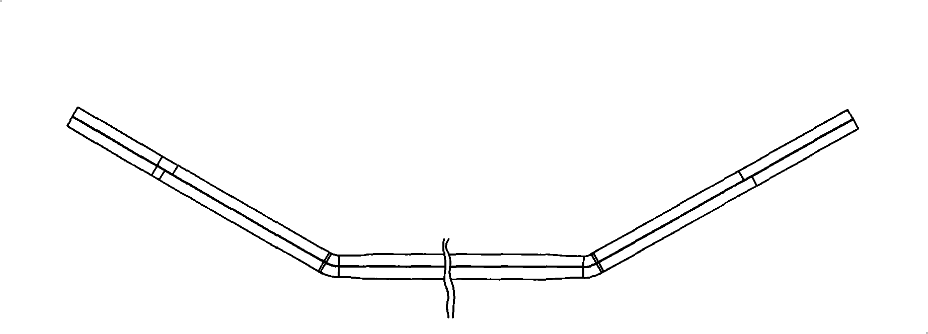
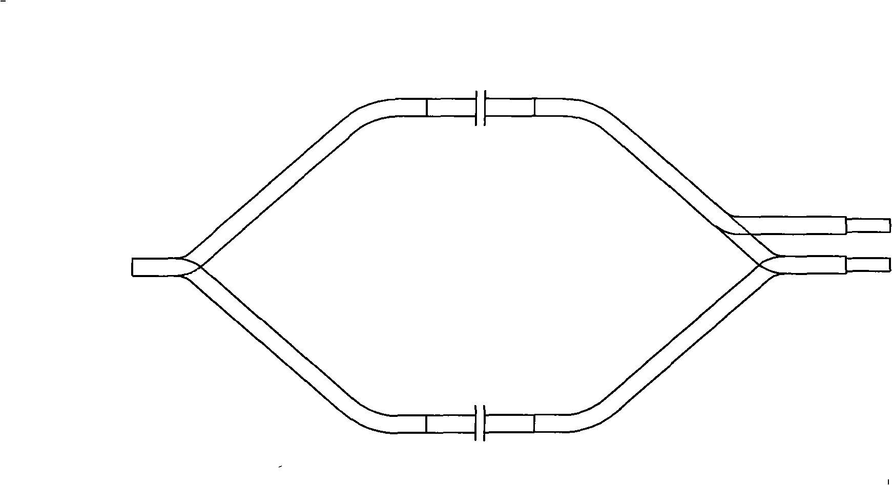
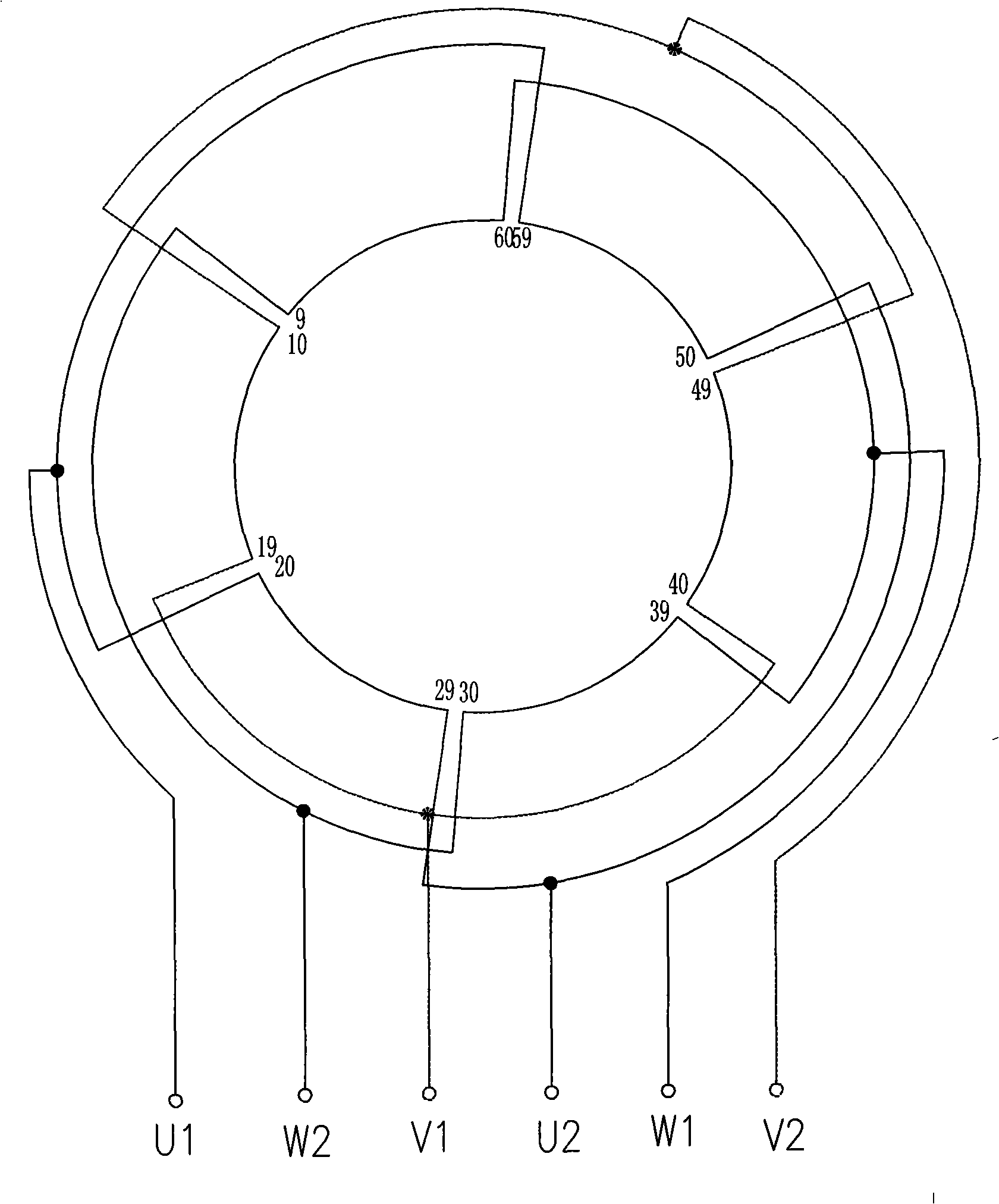
[0030] figure 2 is the structure diagram of a conventional winding.

[0031] Figure 4 It is a structural diagram of the present invention.

[0032] Such as figure 2 , Figure 4 As shown, the two windings are stacked windings, three-phase windings, Y connection, 2 poles, and 2 parallel circuits. U1, V1, W1, U2, V2, and W2 are lead-out wires, and the two windings are manufactured counterclockwise when viewed from the wire-out end. When the number of lead-out wires is 3, U2, V2, and W2 are connected internally without leading out; when th...


PUM


Abstract

A ring dispersal winding of a turbonator is connected into a double layer lap winding by a coil. One to three end coil sides of each pole-phase group and the corresponding coil side of the adjacent phase group mutually exchange the connection of coil ends, and consequently the electric phase angle is locally replaced. The coil is a ring coil and formed by continuously winding a whole line without a welding point in the middle. The winding can satisfy the actual requirement of an electric network on preventing harmonic wave pollution during the synchronization of a generator and meanwhile dramatically shortens the period of goods delivery, saves the equipment production cost and is very high in reliability.

Description

technical field [0001] The invention relates to a turbogenerator, in particular to a winding of a turbogenerator. Background technique [0002] The stator windings of modern large and medium-sized motors, especially turbogenerators, generally use strip coils. [0003] figure 1 is the structural diagram of the strip coil. [0004] Such as figure 1 As shown, two wire bars are placed in the stator core slot along the height direction. After inserting the wires, the wire rods are connected to each other by fiber welding to form a double-layer winding. Each bar consists of a single copper strand of small cross-section. The strands in the wire bar are arranged in two rows along the width direction, and the height direction should be transposed with each other to reduce the eddy current loss. First, each row of strands is pressed out of the transposition bend, and then the transposition braiding is performed. Combine the braided two rows of strands together to form a complete...

Claims


Application Information

Patent Timeline
Patent Type & Authority Applications(China)
IPC IPC(8): H02K3/04H02K3/28
Inventor 刘国徽
Owner SEC ELECTRIC MACHINERY
Why Eureka
Try Eureka