
Portable installation type electronic fence with anti-theft alarm function

An electronic fence, anti-theft alarm technology, applied in anti-theft alarm, anti-theft alarm mechanical start, fence and other directions, can solve the problems of guardrail damage, fence damage, reducing operation efficiency and so on

Active Publication Date: 2021-09-14
上海客欧电子科技有限公司
View PDF11 Cites 1 Cited by
  • Summary
  • Abstract
  • Description
  • Claims
  • Application Information

AI Technical Summary

Problems solved by technology

[0004] The purpose of the present invention is: in order to solve the problem that the existing electronic fences are generally connected together during installation, if one of them is knocked down by impact, there is a high probability that it will affect the tightly fitted surrounding fences, so damage to one fence will Involve other fences, thereby causing greater losses, and the existing guardrails are very troublesome to install and disassemble, which greatly reduces people's operating efficiency. At the same time, if the human body hits the fence and the position fence collapses, the human body will hit the ground, At the same time, it will be damaged by the collision from the fence, which greatly increases the probability of the human body hitting the fence and being seriously injured. A portable electronic fence with anti-theft alarm function is proposed.

Method used


Image

  • Portable installation type electronic fence with anti-theft alarm function
  • Portable installation type electronic fence with anti-theft alarm function
  • Portable installation type electronic fence with anti-theft alarm function

Examples


Embodiment approach

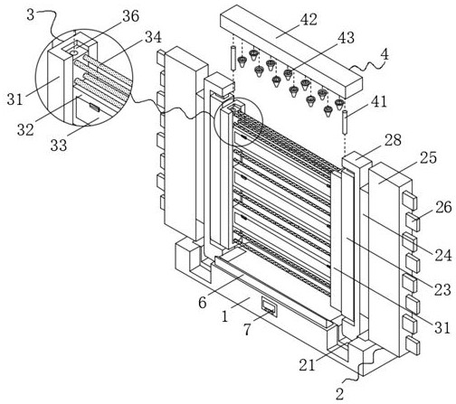
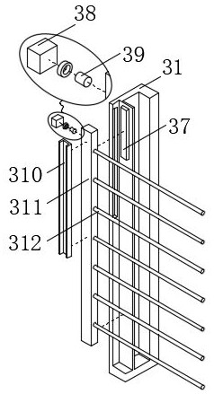
[0045] The specific implementation method is: when the protection area needs to be expanded, the rotation of the fixed bar 311 is controlled so that the fixed bar 311 drives a plurality of second conductive wires 312 to rotate to the upper side of the side plate 31 to expand the protection area. Under the action of a chute, the height of the fixing bar 311 can be adjusted, and the protection area can be effectively adjusted. By setting the U-shaped plate 310 and the magnetic plate 37, the U-shaped plate 310 can be covered on the magnetic plate 37 and can be attracted to each other, so that The fixing bar 311 can be fixed when moved to any position.

[0046] The impurity removal mechanism 4 is arranged on the fence mechanism 3, and the impurity removal mechanism 4 includes a housing 42 fixedly connected to the upper surface of the side plate 31, and the lower surface of the housing 42 communicates with the upper surface of the hollow column 36 through the metal pipe 41. , the f...


PUM


Abstract

The invention discloses a portable installation type electronic fence with an anti-theft alarm function, which belongs to the technical field of electronic fences. The portable installation type electronic fence comprises a bottom plate, the upper surface of the bottom plate is provided with two grooves in bilateral symmetry, the grooves penetrate through the front side face and the rear side face of the bottom plate, positioning grooves are formed in the grooves, and positioning mechanisms are arranged in the positioning grooves. The fence mechanism is arranged, the protection effect can be effectively achieved under the action of the first conductive wire, people are prevented from climbing over the fence, the strength of the first conductive wire can be enhanced through cooperation with the metal shell, and the metal shell can be touched when an object collides with the first conductive wire; the metal shell bears large pressure and can effectively protect the conductive wires from being broken, the position of the second conductive wire can be changed by controlling the position of the fixing strip, the protection range can be effectively expanded by controlling the fixing strip to move upwards so that the second conductive wire can move upwards, and effective adjustment can be achieved according to the actual use condition, and a good protection effect on the area range is achieved.

Description

technical field [0001] The invention belongs to the technical field of electronic fences, and in particular relates to a portable and installed electronic fence with an anti-theft alarm function. Background technique [0002] Electronic fence is currently the most advanced perimeter anti-theft alarm system. The system is mainly composed of three parts: electronic fence host, front-end accessories, and back-end control system. [0003] Existing electronic fences are generally connected together during installation. If one of them is knocked down by impact, it will most likely affect the tightly fitted surrounding fences. Therefore, damage to one fence will implicate other fences, causing even greater damage. The loss of the existing guardrail is very troublesome when installing and disassembling, which greatly reduces the operating efficiency of people. At the same time, if the human body hits the fence and the position fence collapses, the human body will hit the ground and ...

Claims


Application Information

Patent Timeline
IPC IPC(8): G08B13/12E04H17/00
CPCG08B13/122E04H17/00
Inventor 姜毅
Owner 上海客欧电子科技有限公司
Learn More