
Touch screen laminating process and structure

A touch screen and lamination technology, applied in instruments, computing, electrical and digital data processing, etc., can solve the problems of increasing production costs, reducing the transmittance and display clarity of touch screen products, and large lamination thickness.

Pending Publication Date: 2021-09-14
深圳市华仁三和科技有限公司
View PDF2 Cites 0 Cited by
  • Summary
  • Abstract
  • Description
  • Claims
  • Application Information

AI Technical Summary

Problems solved by technology

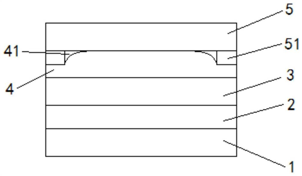
[0002] The touch screen has the characteristics of convenient use, novel appearance and high-tech sense, so it is widely used in various fields. In order to enhance the display effect of the touch screen, the touch screen often adopts a full lamination process, which can greatly increase the overall thickness of the touch screen. Reduced, and at the same time have better display performance, the current bonding of the touch screen adopts such as figure 1 The solid OCA (solid optical adhesive) die-cutting full lamination process shown in the figure has the disadvantages of large lamination thickness, which indirectly reduces the transmittance and display clarity of touch screen products, and large It cannot be completely filled when the gap is broken, resulting in lamination bubbles 41, which reduces the production yield. In addition, it is necessary to customize a special die-cutting mold, which increases production costs

Method used


Image

  • Touch screen laminating process and structure
  • Touch screen laminating process and structure
  • Touch screen laminating process and structure

Examples


Embodiment

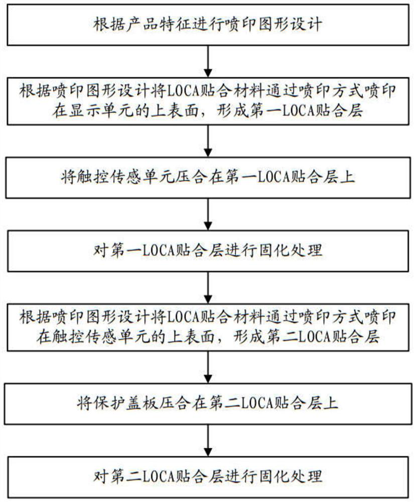
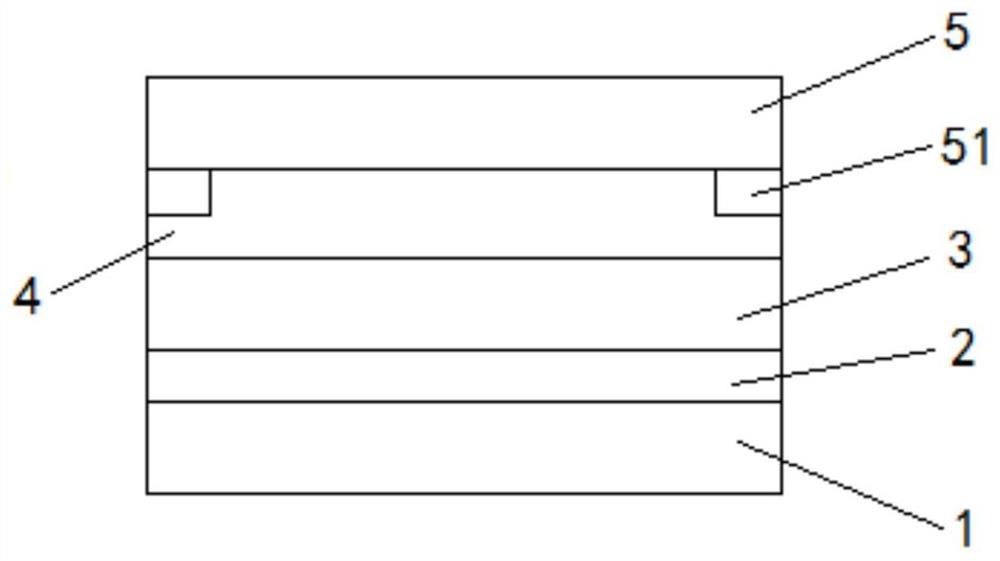
[0035] see figure 2 and image 3 , a touch screen bonding process, comprising:

[0036] S1. Carry out printing graphic design according to product features;

[0037] Specifically, it includes the design of the area where the LOCA bonding material is printed and the thickness of the corresponding printing LOCA bonding material in different areas.

[0038] S2. Print the LOCA bonding material on the upper surface of the display unit by spray printing according to the graphic design of the spray printing to form the first LOCA bonding layer;

[0039] Since the LOCA bonding material is a liquid bonding material, the jet printing equipment can print on the upper surface of the display unit to form a layer of LOCA bonding layer with a uniform thickness through precise printing volume control. The OCA fit layer is thinner and more uniform.

[0040] The thickness of the first LOCA bonding layer is 50-100 nm, which can ensure the bonding effect of the display unit and the touch sen...


PUM

PropertyMeasurementUnit
Viscosityaaaaaaaaaa
Thicknessaaaaaaaaaa

Abstract

The invention provides a touch screen laminating process and structure. The touch screen laminating process comprises the following steps: S1, carrying out jet printing pattern design according to product characteristics; S2, jet-printing an LOCA bonding material on the upper surface of the display unit in a jet-printing manner according to the jet-printing graphic design to form a first LOCA bonding layer; S3, pressing the touch sensing unit on the first LOCA laminating layer; S4, carrying out curing treatment on the first LOCA laminating layer; S5, according to the jet printing pattern design, jet printing an LOCA bonding material on the upper surface of the touch sensing unit in a jet printing mode to form a second LOCA bonding layer; S6, pressing the protective cover plate on the second LOCA laminating layer; and S7, carrying out curing treatment on the second LOCA laminating layer. The process has the beneficial effects that the process for jet printing the attaching layer on the product in a jet printing mode is provided, the mold opening cost and the mold opening manufacturing time are reduced, the attaching quality, the attaching efficiency and the yield are greatly improved by accurately controlling the jet printing quantity and the accurate position for jet printing, and benefit maximization is achieved.

Description

technical field [0001] The invention relates to the technical field of touch screen manufacturing, in particular to a bonding process and structure of a touch screen. Background technique [0002] The touch screen has the characteristics of convenient use, novel appearance and high-tech sense, so it is widely used in various fields. In order to enhance the display effect of the touch screen, the touch screen often adopts a full lamination process, which can greatly increase the overall thickness of the touch screen. Reduced, and at the same time have better display performance, the current bonding of the touch screen adopts such as figure 1 The solid OCA (Solid Optical Adhesive) die-cutting full lamination process shown in the figure has the disadvantages of large lamination thickness, which indirectly reduces the transmittance and display clarity of touch screen products, and large When the gap is broken, it cannot be completely filled, resulting in lamination bubbles 41, ...

Claims


Application Information

Patent Timeline
IPC IPC(8): G06F3/041
CPCG06F3/0412G06F2203/04103
Inventor 胡晓斌
Owner 深圳市华仁三和科技有限公司
Learn More