


Quick Research
Generate reliable direction feasibility study reports for your R&D in just a few steps.

Technical Q&A
Discover and master advanced knowledge NOW. Basics, ideas, possibilities, all at once.

Find Solutions
As an expert in R&D theories, this can generate solutions to your technical problems instantly.

Evaluate Feasibility
Analyze your overall solution with one click, know your potential R&D risks in advance.

Monitor Landscape
Get weekly tech updates, stay abreast of the latest tech innovations and key insights.
Construction site concrete multi-layer pouring frame and construction method
A construction site, concrete technology, applied in the direction of construction, building structure, building materials processing, etc., can solve the problems of grout leakage, reduce the quality of concrete columns, cumbersome operation and so on
- Summary
- Abstract
- Description
- Claims
- Application Information
AI Technical Summary
Problems solved by technology
Method used
Image

Examples
Embodiment 1
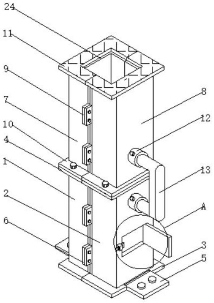
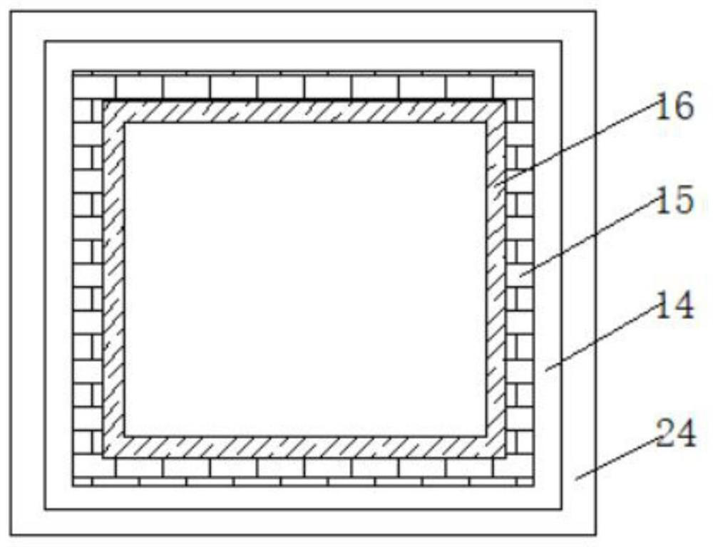
[0019] Example 1: See Figure 1-Figure 4 , the present invention provides a technical solution: a construction site concrete multi-layer pouring frame, including a first formwork 1, a second formwork 2, a third formwork 7, a fourth formwork 8, the first formwork 1, the second formwork 2, The inner surfaces of the third formwork 7 and the fourth formwork 8 are all fixedly connected with a protective layer 24, and the lower surfaces of the first formwork 1 and the second formwork 2 are all fixedly connected with a first base plate 3, and the surfaces of the two first base plates 3 are uniform. There are first grooves, and the inner sides of the two first grooves are movably connected with mounting plates 5, and the upper surfaces of the two mounting plates 5 are symmetrically fixedly connected with rivets, and the upper surfaces of the first template 1 and the second template 2 The surface is fixedly connected with the first top plate 4, the front side surface of the second temp...
Embodiment 2
[0020] Embodiment 2: A further improved solution based on Embodiment 1: both the fourth template 8 and the front side surface of the second template 2 are fixedly connected with installation sleeves 12, and the two installation sleeves 12 are connected by a support frame 13, and the two The outer surface of the mounting sleeve 12 is fixedly connected with a fourth fastening bolt, and the support frame 13 can connect the fourth formwork 8 and the second formwork 2 to improve stability. The user loosens the fourth fastening bolt, and the support frame 13 The disassembly is simple and convenient to operate, which improves the disassembly work efficiency.
Embodiment 3
[0021] Embodiment 3: A further improved solution based on Embodiment 2: the upper surfaces of the two first top plates 4 and the two second top plates 11 are fixedly connected with sealing gaskets, and the sealing gaskets are made of a rubber member, the sealing gaskets The airtightness between the two first top plates 4 and the two second bottom plates 10 can be increased, avoiding the leakage of concrete when pouring concrete, reducing the quality of concrete, and improving the practicability.
PUM
 Abstract
Description
Claims
Application Information
 - R&D Engineer
- R&D Manager
- IP Professional
- Industry Leading Data Capabilities
- Powerful AI technology
- Patent DNA Extraction
Browse by: Latest US Patents, China's latest patents, Technical Efficacy Thesaurus, Application Domain, Technology Topic, Popular Technical Reports.
© 2024 PatSnap. All rights reserved.Legal|Privacy policy|Modern Slavery Act Transparency Statement|Sitemap|About US| Contact US: help@patsnap.com