
Lamp production and processing device

A technology for processing equipment and lamps, which is applied to household appliances, other household appliances, cleaning methods and appliances, etc., and can solve problems such as complicated screw maintenance and cleaning process, delay in work efficiency, and impact on displacement accuracy.

Active Publication Date: 2021-09-10
中山市莱利灯饰股份有限公司
View PDF6 Cites 2 Cited by
  • Summary
  • Abstract
  • Description
  • Claims
  • Application Information

AI Technical Summary

Problems solved by technology

In the production and processing of the lampshade, it is necessary to spin the iron block through the spinning equipment, so that the circular iron sheet is processed into a lampshade. The spinning equipment needs to use the pressing mechanism to shape the circular iron sheet. Spinning the shaped iron sheet into the lampshade requires the pressing mechanism to move forward, backward, left, and right under the control of the program. Nowadays, in order to ensure the stability of the pressing mechanism, a motor is used to drive the screw to rotate, and the screw drives the pressing mechanism to move. The two sets of motor screws are distributed at 90 degrees, which can respectively drive the pressing mechanism to move left and right and forward and backward. However, during the spinning process of the circular iron sheet, a large amount of waste will be generated, and these wastes are easy to adhere to the screw. The surface of the screw enters the thread of the screw, thereby causing damage to the screw and affecting the displacement accuracy. Seriously, the entire spinning equipment cannot work. Therefore, it is necessary for the staff to clean and maintain the screw regularly. However, the maintenance and cleaning process of the screw is very complicated and seriously increases. Increased the workload of the staff and delayed work efficiency

Method used


Image

  • Lamp production and processing device
  • Lamp production and processing device
  • Lamp production and processing device

Examples


Embodiment Construction

[0026] In order to enable those skilled in the art to better understand the present invention, the technical solution of the present invention will be further described below in conjunction with the accompanying drawings and embodiments.

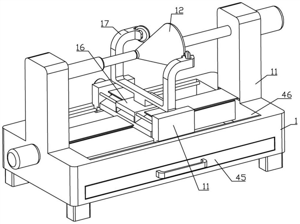
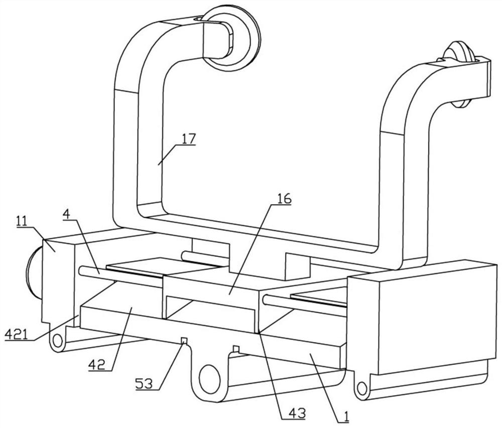
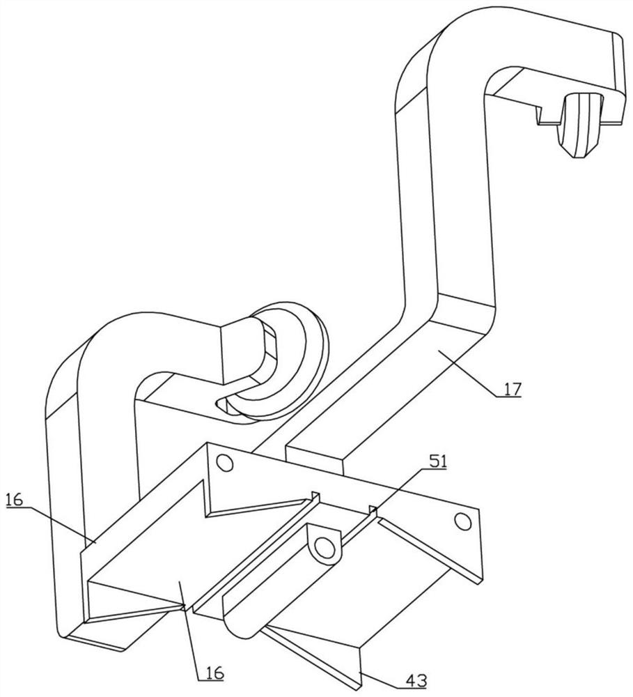
[0027] Such as Figure 1-8 As shown, a lamp production and processing equipment of the present invention includes two mounting plates 1, and support plates 11 are provided at both ends of the two mounting plates 1, and support plates 11 on the left and right sides of the lower mounting plate 1 are provided with Spinning mechanism 12, two mounting plates 1 are distributed up and down and are at 90 degrees to each other. Both mounting plates 1 are provided with chute 13 on the upper side, and screw rods 14 are rotated in the two chute 13. The two screw rods 14 One end transmission is equipped with a motor 15, the upper side mounting plate 1 is threadedly connected with the screw rod 13 on the lower side, the screw rod 14 installed on the upper...


PUM


Abstract

The invention belongs to the technical field of lamp production, and particularly relates to a lamp production and processing device. The lamp production and processing device comprises two mounting plates, a spinning mechanism is arranged between supporting plates on the left side and the right side of the lower mounting plate, the two mounting plates are vertically distributed and form a 90-degree angle, a motor is assembled at one end of each screw in a transmission mode, abutting mechanisms matched with the spinning mechanism are assembled on the left side and the right side of a sliding plate, each shielding mechanism comprises a rotating rod, two torsional springs, two shielding covers and shielding cloth, each supporting plate is provided with a mounting cavity, the rotating rods are rotationally assembled in the mounting cavities, the two torsional springs are arranged in the two shielding covers respectively and assembled with the rotating rod, the shielding cloth is fixedly connected with the middle of the rotating rod, the other end of the shielding cloth extends out of the mounting cavity through an extension opening, the shielding cloth of the lower shielding mechanism extends out of the mounting cavity and is fixedly connected with the upper mounting plate, the shielding cloth of the upper shielding mechanism extends out of the mounting cavity and is fixedly connected with the sliding plate, and the end, extending out of the mounting cavity, of the shielding cloth is located over a sliding groove.

Description

technical field [0001] The invention belongs to the technical field of lamp production, and in particular relates to a lamp production and processing equipment. Background technique [0002] The lampshade is an indispensable part of the lamp. The lampshade not only covers the lamp to gather the light, but also prevents electric shock and protects the eyes. Therefore, there will be a lampshade on the lamp. In the production and processing of the lampshade, it is necessary to spin the iron block through the spinning equipment, so that the circular iron sheet is processed into a lampshade. The spinning equipment needs to use the pressing mechanism to shape the circular iron sheet. Spinning the shaped iron sheet into the lampshade requires the pressing mechanism to move forward, backward, left, and right under the control of the program. Nowadays, in order to ensure the stability of the pressing mechanism, a motor is used to drive the screw to rotate, and the screw drives the pr...

Claims


Application Information

Patent Timeline
IPC IPC(8): B21D22/18B21D51/10B08B17/04
CPCB21D22/18B21D51/10B08B17/04
Inventor 安金波黄官明韦礼杰王斌
Owner 中山市莱利灯饰股份有限公司
Learn More