
Metal silicon production equipment with automatic screening function

A technology of production equipment and functions, which is applied in the field of metal silicon production equipment with automatic screening function, and can solve the problems of low screening efficiency, complex structure of screening device, large floor space, etc.

Inactive Publication Date: 2021-09-10
济南鹏程硅业有限公司
View PDF0 Cites 0 Cited by
  • Summary
  • Abstract
  • Description
  • Claims
  • Application Information

AI Technical Summary

Problems solved by technology

[0003] In view of the deficiencies in the prior art above, the purpose of the present invention is to provide a metal silicon production equipment with automatic screening function, which can solve the problem that the existing screening devices are screened manually, and the screening efficiency is low. , and the existing screening device is complex in structure, expensive in cost, and occupies a large area of ​​technical problems

Method used


Image

  • Metal silicon production equipment with automatic screening function
  • Metal silicon production equipment with automatic screening function
  • Metal silicon production equipment with automatic screening function

Examples


Embodiment 1

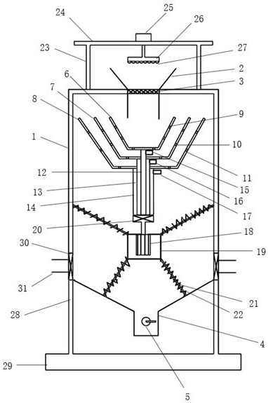
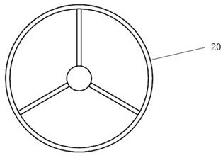
[0029] Such as figure 1 , as shown in 3, a metal silicon production equipment with automatic screening function, comprising a box body 1, a feed hopper 2 is arranged at the center of the top of the box body 1, a vibrating screen 3 is installed in the feed hopper 2, The bottom of the box body 1 is provided with a discharge pipe 4, the discharge pipe 4 is equipped with a discharge valve 5, the inside of the box body 1 is provided with a screening mechanism, and the screening mechanism is located at the bottom of the feed hopper 2. Directly below, the lower end of the screening mechanism is connected with a driving mechanism.

[0030] Further, in the above-mentioned technical scheme, metal silicon enters the box body 1 from the feed hopper 2, and the bulk silicon contained in the silicon is screened out through the vibrating screen 3, and the rest of the silicon powder falls into the screening mechanism for multiple processing. Stage screening, the driving mechanism provides pow...

Embodiment 2

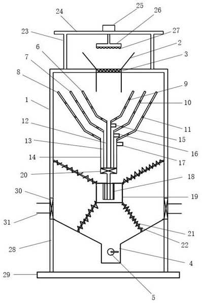
[0046] Such as figure 2 As shown, the bottom of the sieving tank is inclined, with the horizontal line as the reference, the angle of inclination is 45°.

[0047] Further, in the above technical solution, by setting the bottom of the screening tank inclined, it is convenient to increase the feeding speed, thereby improving the production efficiency.

[0048] Working principle: first close the first solenoid valve 15, the second solenoid valve 16, the third solenoid valve 17 and the discharge valve 5, turn on the hot air blower 30, and heat the airflow entering the box body 1 through the air inlet pipe 31, so that the box body The inside of the body 1 maintains a certain temperature. The metal silicon enters from the feed hopper 2, and under the action of the vibrating screen 3, the bulk silicon is screened out and stays on the screen of the vibrating screen 3, and the small particle powder enters the screening mechanism in the box 1 after passing through the vibrating screen...


PUM


Abstract

The invention discloses metal silicon production equipment with an automatic screening function, and relates to the technical field of metallic silicon production. The metal silicon production equipment comprises a box body, a feeding hopper is arranged in the center of the top of the box body, a vibrating screen is installed in the feeding hopper, a discharging pipe is arranged at the bottom of the box body, a discharging valve is installed on the discharging pipe, a screening mechanism is arranged inside the box body, the screening mechanism is located under the feeding hopper, and a driving mechanism is connected to the lower end of the screening mechanism. According to the metal silicon production equipment, the structure is simple, the practicability is high, the automatic screening function can be achieved, silicon powder of different specifications can be screened out according to the requirements of customers, the screening efficiency is high, the precision is high, and the wide market prospect is achieved.

Description

technical field [0001] The invention relates to the technical field of silicon metal production, in particular to silicon metal production equipment with an automatic screening function. Background technique [0002] Metal silicon powder refers to the raw material used in refractory materials and powder metallurgy industry. After the metal silicon powder is produced, it needs to be screened to separate the larger particles from the smaller particles. When the existing screening devices are working, many of them are manually screened, and the screening efficiency is low. The existing screening device is complex in structure, expensive in cost, and occupies a large area. Contents of the invention [0003] In view of the deficiencies in the prior art above, the purpose of the present invention is to provide a metal silicon production equipment with automatic screening function, which can solve the problem that the existing screening devices are screened manually, and the scr...

Claims


Application Information

Patent Timeline
IPC IPC(8): B07B1/28B07B1/42B07B1/46H02K5/24B02C1/00B02C1/14B02C23/16F26B21/00
CPCB07B1/28B07B1/42B07B1/46B07B1/4663H02K5/24B02C1/005B02C1/14B02C23/16F26B21/004B07B2201/04B02C2023/165
Inventor 庄肃鹏姜生芹
Owner 济南鹏程硅业有限公司
Learn More