A three-dimensional optical coherence elastography detection device for corneal refractive surgery
A technology of refractive surgery and three-dimensional optics, which is applied in the field of three-dimensional optical coherent elastic imaging detection devices, can solve problems such as time-consuming and energy-consuming, affect detection results, and contamination of debris, and achieve the effect of improving work efficiency
- Summary
- Abstract
- Description
- Claims
- Application Information
AI Technical Summary
Problems solved by technology
Method used
Image
Examples
Embodiment 1
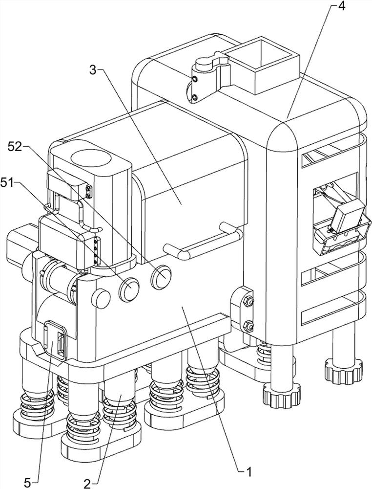
[0089] A three-dimensional optical coherence elastography detection device applied to corneal refractive surgery, such as Figure 1-Figure 6 As shown, it includes a detection box 1, a buffer base 2, a shading cover 3, a protective cover 4, a start button 51, a stop button 52, a material transport mechanism 6 and a detection mechanism 7. The bottom of the detection box 1 is provided with multiple The buffer base 2, the top left side of the detection box 1 is provided with a shading cover 3, the right side of the detection box 1 is provided with a protective cover 4, the upper left side of the detection box 1 is provided with a start button 51, the upper front of the detection box 1 is provided with a start button 51, A stop button 52 is provided on the left side, and the stop button 52 is located on the right side of the start button 51 .
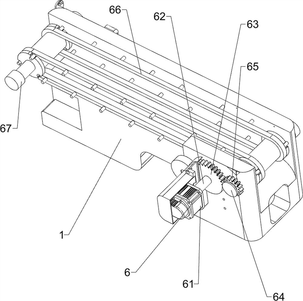
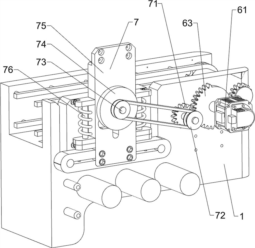
[0090] The conveying mechanism 6 includes a servo motor 61, a drive shaft 62, a missing drive gear 63, a first horizontal shaft 64, a first...
Embodiment 2
[0094] On the basis of Example 1, as Figure 7-Figure 15 As shown, it also includes a feeding mechanism 8. The feeding mechanism 8 includes a charging cylinder 81, a safety baffle 82, a lifting and tilting block frame 83, a return spring column 84, a positioning top plate 85, a material blocking tongue 86, and a water tank 87. , atomizing device 88, air duct 89 and first pressure sensor 810, a charging cylinder 81 is provided on the left side of the top of the detection box 1, the charging cylinder 81 is located on the left side of the shading cover 3, and the lower part of the left side of the charging cylinder 81 is provided There is a safety baffle 82, a positioning top plate 85 is provided on the lower left side of the charging cylinder 81, the positioning top plate 85 is located inside the safety baffle 82, and four return spring columns 84 are arranged at intervals on the left side of the bottom of the positioning top plate 85, and the bottom of the return spring column 8...
PUM
 Abstract
Description
Claims
Application Information
 - R&D
- Intellectual Property
- Life Sciences
- Materials
- Tech Scout
- Unparalleled Data Quality
- Higher Quality Content
- 60% Fewer Hallucinations
Browse by: Latest US Patents, China's latest patents, Technical Efficacy Thesaurus, Application Domain, Technology Topic, Popular Technical Reports.
© 2025 PatSnap. All rights reserved.Legal|Privacy policy|Modern Slavery Act Transparency Statement|Sitemap|About US| Contact US: help@patsnap.com


