Armrest horizontal limiting device, seat and automobile

A horizontal limit and armrest technology, which is applied in the direction of armrests, vehicle seats, special positions of vehicles, etc., can solve the problems affecting the comfort of passengers and the inability to maintain the level of armrests

Active Publication Date: 2021-09-07
SCI SEATING (NINGBO) CO LTD
View PDF7 Cites 2 Cited by
  • Summary
  • Abstract
  • Description
  • Claims
  • Application Information

AI Technical Summary

Problems solved by technology

Solve the problem in the prior art that the armrest cannot be kept horizontal after the seat back is turned, which affects the comfort of passengers

Method used


Image

  • Armrest horizontal limiting device, seat and automobile
  • Armrest horizontal limiting device, seat and automobile
  • Armrest horizontal limiting device, seat and automobile

Examples


Embodiment 1

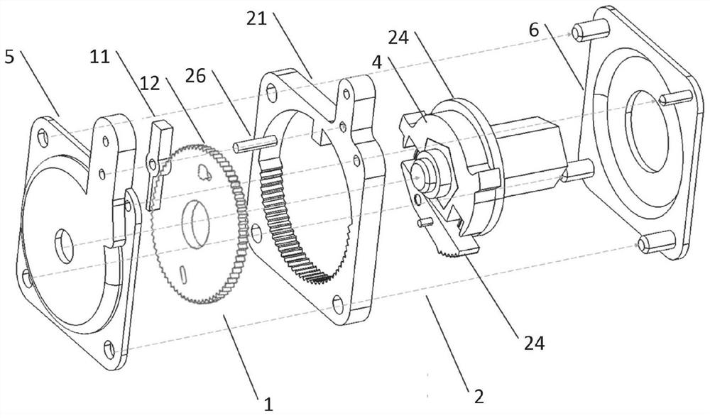
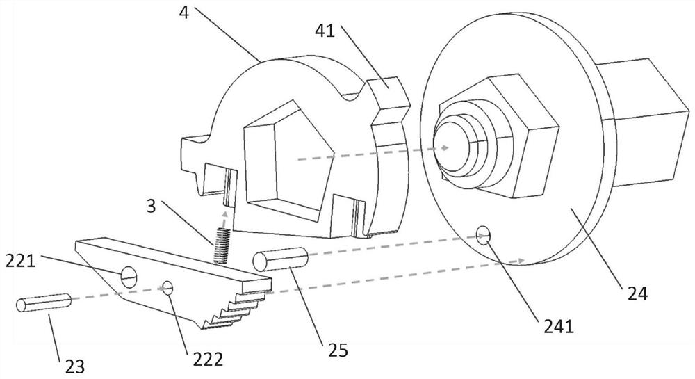
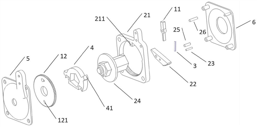
[0035] Such as Figure 1-3As shown, a handrail level limiting device, the limiting device is used to be assembled in the armrest, so that the armrest can be adjusted to maintain a horizontal state, the limiting device includes a gravity component 1 and a ratchet component 2, the gravity component 1 is used for Control the unlocking and locking of the ratchet assembly 2, the ratchet assembly 2 includes a ratchet lock plate 21, a ratchet swing tooth 22, a ratchet swing tooth unlocking shaft 23 and a main shaft 24, the ratchet swing tooth 22 meshes with the ratchet lock plate 21, and the ratchet lock plate 21 is used for Control the rotation and stop of the armrest, the armrest is connected to the main shaft 24 in rotation, the ratchet swing tooth 22 is connected to the main shaft 24 in rotation, the gravity assembly 1 includes a gravity lock 11 and a gravity lock disc 12, and the gravity lock 11 is rotatably connected to the ratchet lock disc 21, When the gravity lock 11 is in t...

Embodiment 2

[0061] A seat, characterized in that it includes an armrest and the armrest level limiting device as described in Embodiment 1. Taking the passenger’s seating position as the reference, the left armrest of the seat corresponds to the position close to the passenger’s left hand, and the right armrest of the seat corresponds to the position of the passenger’s left hand. Close to the passenger's right hand position, the armrest level limiting device described in Embodiment 1 is installed on the left armrest of the seat, and the main shaft 24 protruding from the round hole on the inner shell 6 is used to install on the left side of the seat The end face, that is, the central axis of the main shaft is perpendicular to the left end face of the seat, the inner shell 6 is the side close to the seating position of the seat, and the outer shell 5 is the side away from the seating position of the seat; when the When the armrest level limiting device is installed on the right armrest of th...


PUM


Abstract

The invention relates to an armrest horizontal limiting device, a seat and an automobile. The limiting device comprises a gravity assembly and a ratchet wheel assembly, the gravity assembly is used for controlling unlocking and locking of the ratchet wheel assembly, and the ratchet wheel assembly comprises a ratchet wheel lock disc, ratchet wheel swing teeth, a ratchet wheel swing tooth unlocking rotating shaft and a main shaft; the ratchet wheel assembly comprises ratchet wheel swing teeth and a ratchet wheel lock disc, the ratchet wheel swing teeth are meshed with the ratchet wheel lock disc, the ratchet wheel lock disc is used for controlling a handrail to rotate, the ratchet wheel swing teeth are rotationally connected with the main shaft, the gravity assembly comprises a gravity lock and a gravity lock disc, the gravity lock is fixedly installed on the ratchet wheel lock disc, and the gravity lock is meshed with the gravity lock disc when located at the first position; the gravity lock disc is fixedly connected with the main shaft, and the ratchet swing teeth are rotationally connected around the ratchet swing tooth unlocking rotating shaft. Through cooperation of the gravity assembly and the ratchet wheel assembly, the one-way locking function of the handrail is achieved; and the problem that in the prior art, after a seat backrest rotates, armrests cannot be kept horizontal, and the comfort of passengers is affected is solved.

Description

technical field [0001] The invention relates to the technical field of automobile armrest parts, in particular to an armrest level limiting device, a seat and an automobile. Background technique [0002] The armrest of a car seat is an area of ​​high concern for passengers in daily use. The comfort of the armrest is directly related to the embodiment of ergonomics, thus affecting the ergonomic performance and market competitiveness of related models. Therefore, assessing the state of use of armrests is an important part of the vehicle development process. At present, the common car seat armrests on the market are mainly fixed armrests. The horizontal state of the armrests is designed according to the normal sitting posture of ordinary people. The relative locking angle between the armrests of the seat back and the backrest is fixed. The design is not humanized enough, and it is difficult to meet the comfort requirements of different users. [0003] The use of horizontal li...

Claims


Application Information

Patent Timeline
IPC IPC(8): B60N2/75
CPCB60N2/767
Inventor 雷聪明可锐米立峰张建民
Owner SCI SEATING (NINGBO) CO LTD
Why Eureka
Try Eureka