An irregular circuit board angle cutting equipment
A circuit board and irregular technology, which is applied in the field of irregular circuit board cutting angle equipment, can solve the problems of poor quality of cutting angle and slow cutting speed, and achieve good quality of cutting angle, accurate cutting angle of circuit board and good quality Effect
- Summary
- Abstract
- Description
- Claims
- Application Information
AI Technical Summary
Problems solved by technology
Method used
Image
Examples
Embodiment 1
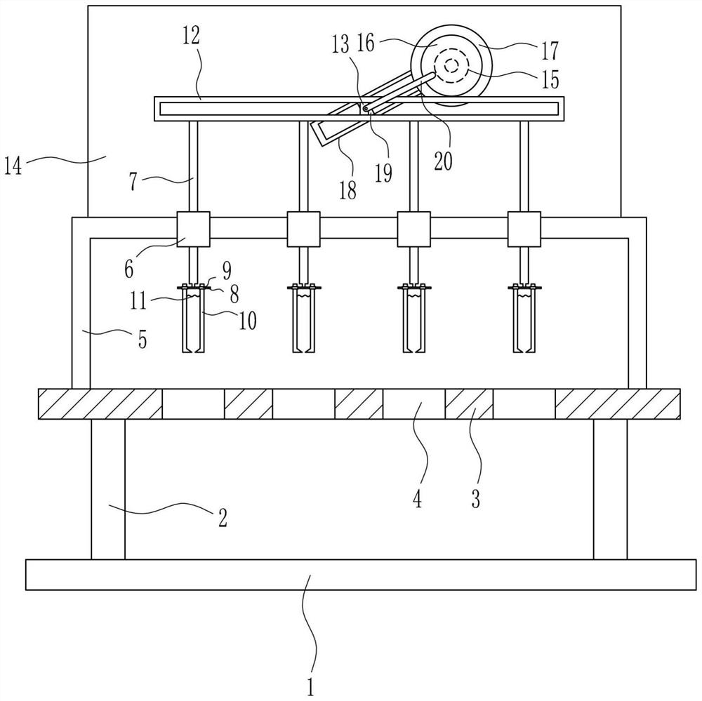
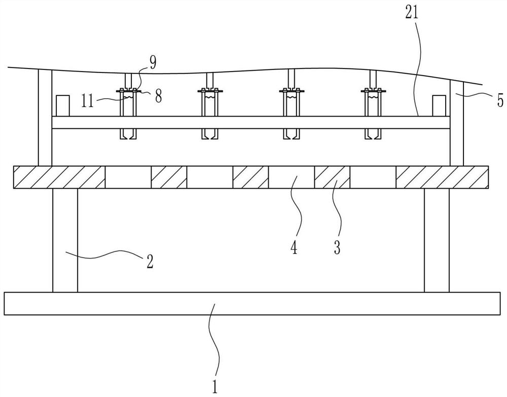
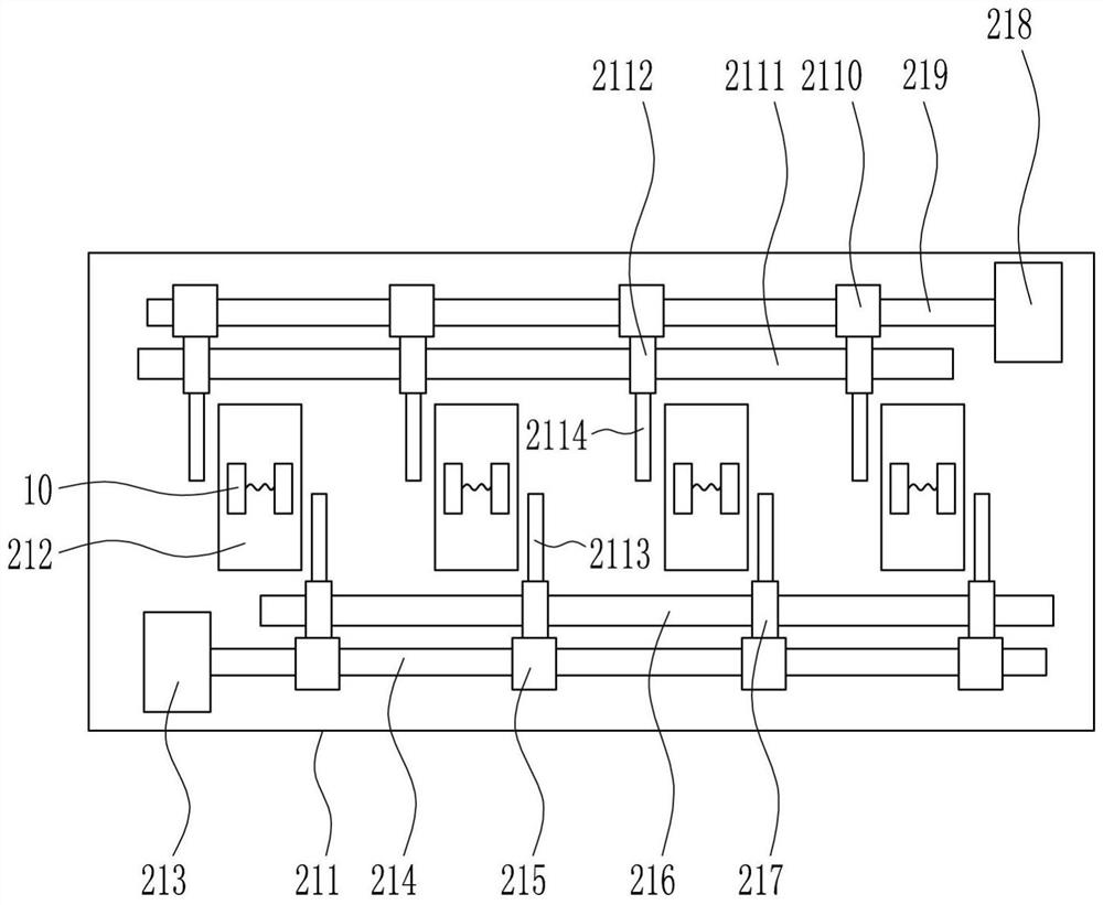
[0028] An irregular circuit board corner cutting device, such as Figure 1-6 As shown, it includes a base plate 1, a support rod 2, a placing plate 3, a mounting frame 5, a first guide sleeve 6, a first guide rod 7, a second guide rod 8, a second guide sleeve 9, a blade 10, a first spring 11. The first guide rail 12, the first slider 13, the first mounting plate 14, the first motor 15, the disk 16, the ring 17, the second guide rail 18, the second slider 19 and the connecting rod 20, the top of the bottom plate 1 The left and right sides are provided with support rods 2, the top of the support rod 2 is connected with a placement plate 3, the top of the placement plate 3 is provided with a mounting frame 5, the placement plate 3 is provided with four first through holes 4, and the mounting frame 5 is provided with The wall is provided with four first guide sleeves 6, the first guide sleeve 6 is sleeved with a first guide rod 7, the bottom end of the first guide rod 7 is connect...
Embodiment 2
[0030] An irregular circuit board corner cutting device, such as Figure 1-6 As shown, it includes a base plate 1, a support rod 2, a placing plate 3, a mounting frame 5, a first guide sleeve 6, a first guide rod 7, a second guide rod 8, a second guide sleeve 9, a blade 10, a first spring 11. The first guide rail 12, the first slider 13, the first mounting plate 14, the first motor 15, the disk 16, the ring 17, the second guide rail 18, the second slider 19 and the connecting rod 20, the top of the bottom plate 1 The left and right sides are provided with support rods 2, the top of the support rod 2 is connected with a placement plate 3, the top of the placement plate 3 is provided with a mounting frame 5, the placement plate 3 is provided with four first through holes 4, and the mounting frame 5 is provided with The wall is provided with four first guide sleeves 6, the first guide sleeve 6 is sleeved with a first guide rod 7, the bottom end of the first guide rod 7 is connect...
Embodiment 3
[0033] An irregular circuit board corner cutting device, such as Figure 1-6 As shown, it includes a base plate 1, a support rod 2, a placing plate 3, a mounting frame 5, a first guide sleeve 6, a first guide rod 7, a second guide rod 8, a second guide sleeve 9, a blade 10, a first spring 11. The first guide rail 12, the first slider 13, the first mounting plate 14, the first motor 15, the disk 16, the ring 17, the second guide rail 18, the second slider 19 and the connecting rod 20, the top of the bottom plate 1 The left and right sides are provided with support rods 2, the top of the support rod 2 is connected with a placement plate 3, the top of the placement plate 3 is provided with a mounting frame 5, the placement plate 3 is provided with four first through holes 4, and the mounting frame 5 is provided with The wall is provided with four first guide sleeves 6, the first guide sleeve 6 is sleeved with a first guide rod 7, the bottom end of the first guide rod 7 is connect...
PUM
 Abstract
Description
Claims
Application Information
 - R&D
- Intellectual Property
- Life Sciences
- Materials
- Tech Scout
- Unparalleled Data Quality
- Higher Quality Content
- 60% Fewer Hallucinations
Browse by: Latest US Patents, China's latest patents, Technical Efficacy Thesaurus, Application Domain, Technology Topic, Popular Technical Reports.
© 2025 PatSnap. All rights reserved.Legal|Privacy policy|Modern Slavery Act Transparency Statement|Sitemap|About US| Contact US: help@patsnap.com


