Fluidized soil backfilling equipment with screening function

A technology of backfilling and screening, which is applied to clay preparation devices, screening, solid separation, etc., can solve the problems of low degree of automation, achieve the effect of improving utilization rate, increasing integration degree and automation level, and compact structure

Pending Publication Date: 2021-09-07
WUHAN POWER EQUIP WORKS
View PDF1 Cites 1 Cited by
  • Summary
  • Abstract
  • Description
  • Claims
  • Application Information

AI Technical Summary

Problems solved by technology

[0005] The purpose of the present invention is to overcome the problem of low degree of automation existing in the prior art, and to provide a fluidized backfill equipment with a high degree of automation with a screening function

Method used


Image

  • Fluidized soil backfilling equipment with screening function
  • Fluidized soil backfilling equipment with screening function
  • Fluidized soil backfilling equipment with screening function

Examples


Embodiment 1

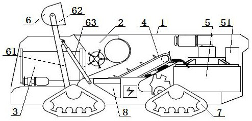
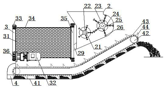
[0049] A fluidized backfill equipment with a screening function, the fluidized backfill equipment includes: a housing 1 and a crushing mechanism 2 arranged in the housing 1, a screening mechanism 3, a chain rake conveying mechanism 4 and a mixing The stirring mechanism 5, the chain rake conveying mechanism 4 and the mixing and stirring mechanism 5 are fixed on the floor in the housing 1, and the discharge end of the chain rake conveying mechanism 4 is arranged above the feeding port of the mixing and stirring mechanism 5, so The screening mechanism 3 is arranged above the feeding end of the chain rake conveying mechanism 4, and the shell 1 on the side of the chain rake conveying mechanism 4 is provided with a cement feeding port 8, and the crushing mechanism 2 is arranged on the screening mechanism 3 Between the mixing and stirring mechanism 5, the discharge port of the crushing mechanism 2 is set facing the inside of the screening mechanism 3, and the feed port of the crushing...

Embodiment 2

[0051] Embodiment 2 is basically the same as Embodiment 1, and its difference is:

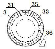
[0052] The screening mechanism 3 is a roller screening mechanism.

[0053] Both sides of the bottom of the housing 1 are respectively provided with two sets of crawler running devices 7, the crawler running devices 7 are driven by hydraulic motors or diesel engines, and the sides of the crawler running devices 7 are connected to the bottom of the housing 1 through hydraulic lifting cylinders. connected.

Embodiment 3

[0055] Embodiment 3 is basically the same as Embodiment 2, and its difference is:

[0056] The feeding mechanism 6 includes a rotating arm 61 and a hopper 62. Both sides of the housing 1 are respectively connected to the side of the hopper 62 through a rotating arm 61. The lower end of the rotating arm 61 is connected to the side of the housing 1. The side part is rotationally matched, the upper end of the pivoting arm 61 is pivotally matched with the hopper 62 , and the side of the housing 1 is connected with the middle part of the pivoting arm 61 through the pivoting arm cylinder 63 .


PUM


Abstract

Fluidized soil backfilling equipment with a screening function comprises a shell, a crushing mechanism, a screening mechanism, a chain harrow conveying mechanism and a mixing and stirring mechanism, the crushing mechanism, the screening mechanism, the chain harrow conveying mechanism and the mixing and stirring mechanism are arranged in the shell, and the chain harrow conveying mechanism and the mixing and stirring mechanism are fixed to a floor in the shell. The discharging end of the chain harrow conveying mechanism is arranged above a feeding port of the mixing and stirring mechanism, the screening mechanism is arranged above the feeding end of the chain harrow conveying mechanism, a cement feeding port is formed in the position, at the side portion of the chain harrow conveying mechanism, of the shell, and the crushing mechanism is arranged between the screening mechanism and the mixing and stirring mechanism. A discharging port of the crushing mechanism is arranged right opposite to the interior of the screening mechanism, and a feeding port of the crushing mechanism is formed in an opening in the top of the shell. According to the design, multiple functions are integrated, and the integration degree and the automation level of the equipment are high.

Description

technical field [0001] The invention relates to a fluidized backfill equipment with a screening function, which is particularly suitable for improving the automation degree of the fluidized backfill equipment. Background technique [0002] After the urban pipeline system is laid, it needs to be backfilled with sandy soil or sand. Because of the narrow space on site, small mechanical or manual methods are often used for tamping, which will often cause the axillary corners of the pipeline to be not compacted in place. The first generation machine of this product is a kind of fluidized soil production equipment ZL201910940897.9, a kind of fluidized soil construction equipment, including: traveling mechanism; The pressing device is installed at one end of the traveling mechanism; the stirring device is used to stir the crushed soil and auxiliary materials to form fluidized soil, and the stirring device is arranged at the other end of the traveling mechanism; the screw conveying...

Claims


Application Information

Patent Timeline
Patent Type & Authority Applications(China)
IPC IPC(8): B02C13/20B02C13/30B02C23/10B07B1/46B28C7/06B28C7/10B28C9/04E02F5/22
CPCB02C13/20B02C13/30B02C23/10B07B1/4609E02F5/22B28C7/0007B28C7/06B28C7/10B28C9/04
Inventor 刘青熊光宝王宝双霍同乾罗浩原
Owner WUHAN POWER EQUIP WORKS
Why Eureka
Try Eureka