Vehicle-mounted 3D surround-view image display method

An image display and 3D technology, applied in the field of computer vision, can solve problems such as ambiguity, increasing system computing complexity, and not mentioning the size of each model, so as to reduce system computing complexity, reduce system resource consumption, and improve display effect of effect

Pending Publication Date: 2021-09-03
苏州易航远智智能科技有限公司
View PDF4 Cites 0 Cited by
  • Summary
  • Abstract
  • Description
  • Claims
  • Application Information

AI Technical Summary

Problems solved by technology

However, the patent does not mention how to determine the size of each model. Different camera installation conditions and scenes require manual adjustment of model parameters, and adaptive adjustment cannot be achieved.
In addition, the method of changing different projection models in real time by sensing the surrounding environment will increase the resource consumption and computing burden of the system, and affect the real-time performance of the surround view screen.
[0005] (3) Chinese patent CN 103065318 A discloses "curved surface projection method and device for multi-camera panoramic system". In this patent, distortion-free images are first obtained through distortion correction, and then a three-dimensional surface model is established. According to the Z-axis coordinates in the three-dimensional surface model The value Zc is unified coordinate transformation, and finally the undistorted image is projected onto the three-dimensional surface model to realize panoramic imaging on the surface. The model is generated according to the formula However, β, a, and b in the formula are not clear
However, this patent needs to rely on the radar sensor to perceive the surrounding environment to correct the fusion angle and fusion range, which increases the computational complexity of the system

Method used


Image

  • Vehicle-mounted 3D surround-view image display method
  • Vehicle-mounted 3D surround-view image display method
  • Vehicle-mounted 3D surround-view image display method

Examples


Embodiment Construction

[0059] The following will clearly and completely describe the technical solutions in the embodiments of the application with reference to the drawings in the embodiments of the application. Apparently, the described embodiments are only some, not all, embodiments of the application. Based on the embodiments in this application, all other embodiments obtained by persons of ordinary skill in the art without making creative efforts belong to the scope of protection of this application.

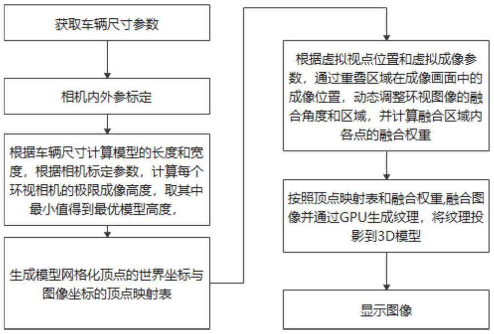
[0060] refer to figure 1 A method for displaying a vehicle-mounted 3D surround-view image provided by the present invention specifically includes the following steps:

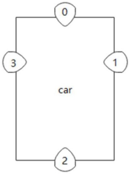
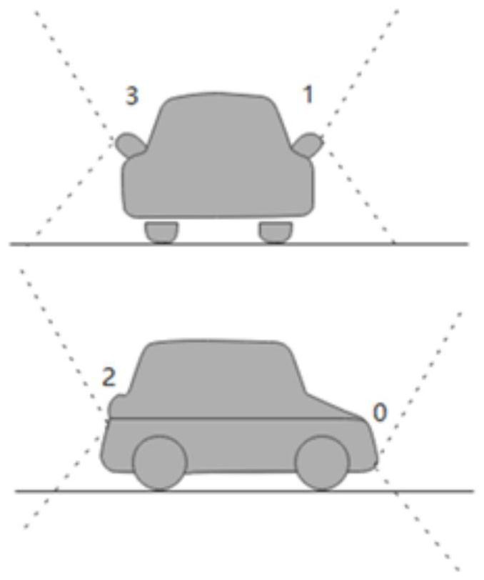
[0061] Step S1, obtain the vehicle size parameters, and calibrate the internal reference matrix and the external matrix of the surround-view camera at the same time; set the vehicle size as [l, w, h], l is the length of the vehicle, w is the width of the vehicle, and h is the height of the vehicle ; The internal parameter matrix ...


PUM


Abstract

The invention relates to a vehicle-mounted 3D look-around image display method, which comprises the following steps of: firstly obtaining vehicle size parameters, calibrating an internal reference matrix and an outer matrix of a look-around camera, then calculating the length and the width of a 3D projection model according to the vehicle size, and generating a 3D projection model with an optimal size according to the calibration parameters of the look-around camera; establishing a gridding vertex coordinate set of the 3D projection model, calculating coordinates of an image coordinate system after each vertex coordinate of the 3D projection model is projected to a corresponding surround view camera under a world coordinate system, and establishing a vertex mapping table of the 3D projection model; according to the virtual viewpoint position and the virtual imaging parameters, dynamically adjusting the fusion angle and the fusion area of the surround view image through the imaging position of the overlapping area in the imaging picture, and calculating the fusion weight of each point in the fusion area; and finally fusing the image according to the vertex mapping table and the fusion weight, and displaying the image. According to the method, the system calculation complexity can be reduced while the look-around display effect is ensured.

Description

technical field [0001] The invention belongs to the technical field of computer vision, and in particular relates to a vehicle-mounted 3D surround-view image display method. Background technique [0002] With the rapid development of computer vision technology and the continuous improvement of mobile hardware processing capabilities, computer vision has been continuously applied in autonomous driving and has gradually played an increasingly important role. Due to its super wide-angle advantages, fisheye cameras are widely used in the vehicle camera market. The most widely used is to use multiple fisheye cameras to construct a panoramic image for driving assistance. At present, the acquisition methods of the look-around panoramic image mainly include the following types: [0003] (1) Chinese patent CN 109741455 A discloses "a vehicle-mounted three-dimensional panoramic display method, computer-readable storage medium and system", which establishes a three-dimensional grid mo...

Claims


Application Information

Patent Timeline
IPC IPC(8): G06T17/00G06T15/04G06T7/40G06T7/80G06T5/50
CPCG06T17/00G06T15/04G06T7/40G06T7/80G06T5/50G06T2207/10028G06T2207/20221
Inventor 邓立凯梁义辉史艳辉
Owner 苏州易航远智智能科技有限公司
Why Eureka
Try Eureka