Eureka AIR delivers breakthrough ideas for toughest innovation challenges, trusted by R&D personnel around the world.

Power supply control system and control method

A technology of power control and power output, applied in general control systems, control/regulation systems, program control, etc., can solve problems such as the inability to realize equipment resource sharing and separate power supply control, achieve convenient and effective management and control, avoid resource waste, avoid Use conflicting effects

Pending Publication Date: 2021-09-03
福建依时利软件股份有限公司
View PDF10 Cites 1 Cited by
  • Summary
  • Abstract
  • Description
  • Claims
  • Application Information

AI Technical Summary

Problems solved by technology

[0003] The technical problem to be solved by the present invention is to provide a power supply control system and control method to solve the problem that the existing power supply controller is difficult to individually control the power supply of each station, and cannot realize the sharing of equipment resources in laboratories or electronic piano rooms question

Method used


Image

  • Power supply control system and control method
  • Power supply control system and control method
  • Power supply control system and control method

Examples


Embodiment 1

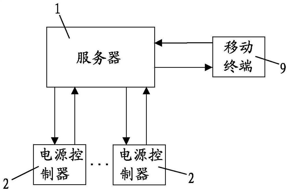
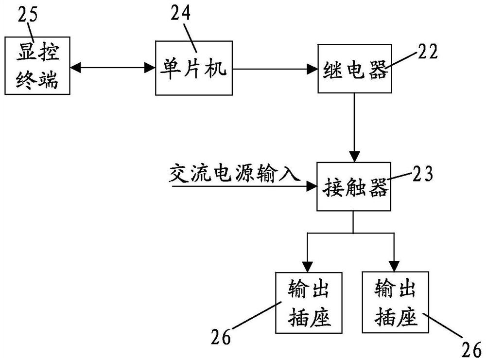
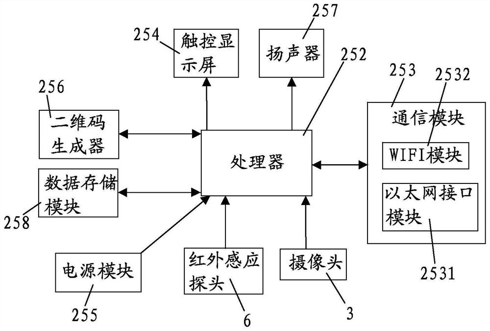
[0062] see Figure 1 to Figure 7 and Figure 9 As shown, the present invention is a power control system, the power control system includes a server 1 and at least one power controller 2 arranged on the workstation and connected to the server 1 in communication, the power controller 2 is used to control the Power supply for the equipment on the bit;

[0063] The power controller 2 includes an outer shell 21, a relay 22, a contactor 23, a single-chip microcomputer 24 and a display and control terminal 25; the relay 22, the contactor 23 and the single-chip microcomputer 24 are all fixed in the outer shell 21; The input end of the contactor 23 is connected to an AC power supply to realize the input of alternating current, and the output end of the contactor 23 is connected to at least one output socket 26 for the output of the station power supply, and the output socket 26 is fixed on the shell The outer surface of the body 21, so as to connect external equipment that needs pow...

Embodiment 2

[0092] see Figure 1 to Figure 9 As shown, a preferred embodiment of a power control method of the present invention, the power control method uses the above-mentioned power control system, the specific structure of the power control system please refer to the introduction in Embodiment 1, and will not be repeated here. The power control method includes:

[0093] The processor 252 controls the two-dimensional code generator 256 to generate a two-dimensional code for turning on the power output of the workstation, and displays the generated two-dimensional code in the first display area 2541;

[0094] After the user arrives at the workstation, the user scans the QR code through the mobile terminal 9 to initiate a power-on request to the server 1. Based on the power-on request, the server 1 judges whether the power-on condition is satisfied. If the power-on condition is satisfied, the server 1 sends the judgment result to To the processor 252, the processor 252 sends a control ...


PUM


Abstract

The invention provides a power supply control system and a control method. The power supply control system comprises a server and at least one power supply controller which is arranged on a station and is in communication connection with the server, the power supply controller comprises an outer shell, a relay, a contactor, a single-chip microcomputer and a display control terminal; the relay, the contactor and the single-chip microcomputer are fixedly arranged in the outer shell; the input end of the contactor is connected with an alternating current power supply, the output end of the contactor is connected with at least one output socket used for outputting a station power supply, and the output socket is fixedly arranged on the outer surface of the outer shell; and the single-chip microcomputer is connected with the contactor through a relay. The system has the advantages that independent control over power supply on each station can be achieved, a user can conveniently start the power supply controller for power supply in a self-service mode, and the power supply use condition of the user can be conveniently and effectively managed and controlled.

Description

【Technical field】 [0001] The invention relates to the field of power control, in particular to a power control system and a control method. 【Background technique】 [0002] The power controller is mainly used for power supply or power-off control of the equipment. In the school's laboratory, electronic piano room and other occasions, it is necessary to use the power controller to control the power supply of the experimental equipment or electronic piano at each station. In the existing laboratory or electronic organ room, the control switch on the power controller is manually toggled to realize the power on and off control; however, it is difficult to control the power supply of each station individually by manual toggle. The sharing of equipment resources in the laboratory or electronic piano room cannot be realized. In view of the above-mentioned problems, the inventor of this case conducted an in-depth study on the problem, and this case arose. 【Content of invention】 ...

Claims


Application Information

Patent Timeline
Patent Type & Authority Applications(China)
IPC IPC(8): G05B19/042G06K19/06
CPCG05B19/0423G06K19/06037G05B2219/25257
Inventor 张宏江良通苏映锦龚万奎胡光银
Owner 福建依时利软件股份有限公司
Why Eureka
Eureka Blog
Learn More