
Water flow on-line measuring device

An online test and water flow technology, which is applied to measuring devices, fluid velocity measurement, liquid/fluid solid measurement, etc., can solve the problems of no better flow measurement method, no real-time online flow measurement, poor data availability, etc., to achieve convenience The effect of measuring water depth, ensuring accuracy, and stabilizing data

Active Publication Date: 2021-09-03
JINAN HEYI HUISHENG TECH DEV CO LTD
View PDF13 Cites 2 Cited by
  • Summary
  • Abstract
  • Description
  • Claims
  • Application Information

AI Technical Summary

Problems solved by technology

[0002] At present, the water flow measurement of open channels mostly adopts the flow velocity area method, the standard section method, the canal system building method and the weir and flume method. There are problems such as low measurement accuracy
In order to realize the accurate measurement of open channel flow, the flow velocity area method is mostly used. The common flow velocity measurement methods include acoustic Doppler, radar, rotor, etc., and the acoustic Doppler has the problem of poor penetration. It is not suitable to be used in places with a lot of water and water impurities; most of the radar types use surface radar current meters to measure the flow velocity at one or more points. Poor; the rotor-type flow meter adopts the mechanical principle, and there are problems such as easy hanging of debris and mechanical wear during the measurement process, and it is generally not used for real-time online flow measurement applications
In addition, for the above flow velocity measurement methods, due to the siltation of open channels, the measurement of water depth needs to be considered separately, and other engineering measures need to be added
[0003] To sum up, there is currently no better way to measure flow in open channels, especially for open channels with poor water quality, turbid water, many floating objects, and easy to silt.

Method used


Image

  • Water flow on-line measuring device
  • Water flow on-line measuring device
  • Water flow on-line measuring device

Examples


Embodiment Construction

[0030] A specific embodiment of the present invention will be described in detail below in conjunction with the accompanying drawings, but it should be understood that the protection scope of the present invention is not limited by the specific embodiment.

[0031] In describing the present invention, it should be understood that the terms "center", "longitudinal", "transverse", "upper", "lower", "front", "rear", "left", "right", The orientations or positional relationships indicated by "vertical", "horizontal", "top", "bottom", "inner", "outer", etc. are based on the orientation or positional relationships shown in the drawings, and are only for the convenience of describing the present invention Creation and simplification of description, rather than indicating or implying that the device or element referred to must have a specific orientation, be constructed and operate in a specific orientation, and therefore should not be construed as limiting the invention.

[0032] The ...


PUM


Abstract

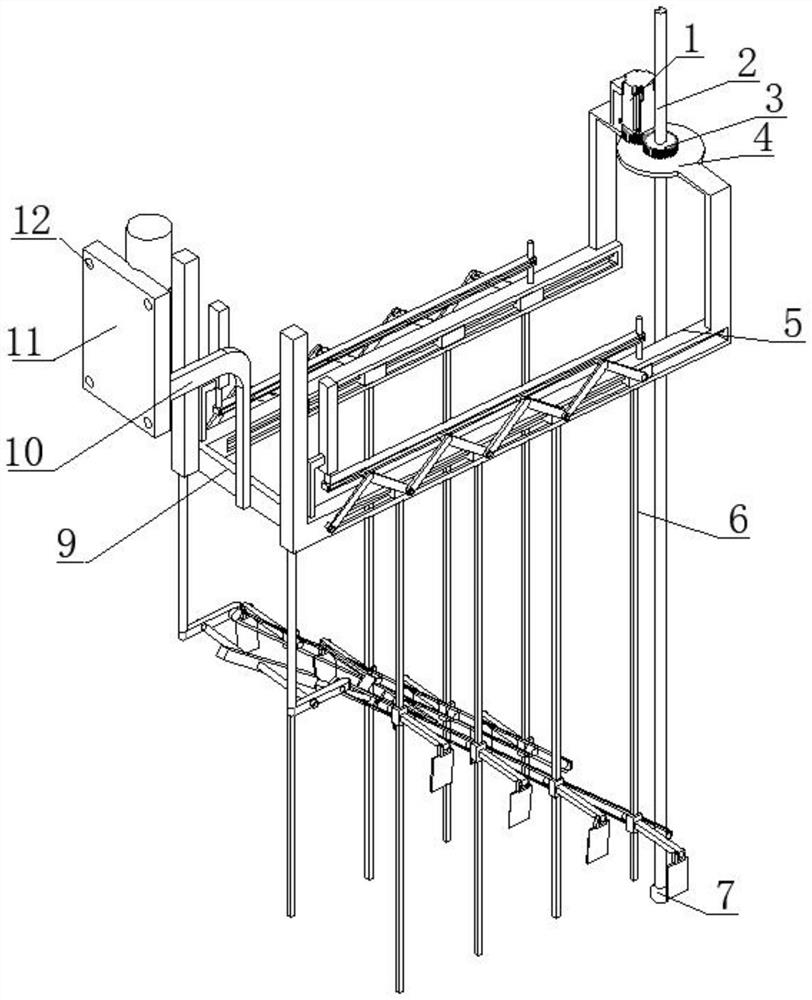
The invention discloses a water flow on-line testing device which comprises a fixing plate, four corners of the fixing plate are respectively provided with mounting holes, and the water flow on-line testing device is characterized in that one side of the fixing plate is fixedly connected with one end of a cross rod of an L-shaped fixing rod, and the other end of the L-shaped fixing rod is fixedly connected with the middle of the cross rod; the two ends of the cross rod are fixedly connected with one ends of the straight groove rods respectively, the other ends of the straight groove rods are fixedly connected with the two ends of the vertical rod of the inverted-U-shaped support respectively, the inverted-U-shaped support is connected with the ditch depth testing module, and the two straight groove rods are connected with the water flow velocity testing module respectively. The invention relates to the technical field of open channel flow measurement, in particular to a water flow online measuring device. The device can conveniently measure the water flow velocity.

Description

technical field [0001] The invention relates to the technical field of open channel flow measurement, in particular to an online water flow measurement device. Background technique [0002] At present, the water flow measurement of open channels mostly adopts the flow velocity area method, the standard section method, the canal system building method and the weir and flume method. There are problems such as low measurement accuracy. In order to realize the accurate measurement of open channel flow, the flow velocity area method is mostly used. The common flow velocity measurement methods include acoustic Doppler, radar, rotor, etc., and the acoustic Doppler has the problem of poor penetration. It is not suitable to be used in places with a lot of water and water impurities; most of the radar types use surface radar current meters to measure the flow velocity at one or more points. Poor; the rotor-type flow meter adopts the mechanical principle, and there are problems such ...

Claims


Application Information

Patent Timeline
Patent Type & Authority Applications(China)
IPC IPC(8): G01P5/00G01C13/00G01F1/00G01B21/18
CPCG01P5/00G01C13/008G01F1/002G01B21/18
Inventor 宋秋英沈东峰李心愉刘琳燕永存杨元军
Owner JINAN HEYI HUISHENG TECH DEV CO LTD
Learn More