Driven wheel floating mechanism and AGV

A floating mechanism and driven wheel technology, applied in vehicle parts, elastic suspensions, suspensions, etc., can solve the problems of large elastic force variation range of compression springs, no positive pressure of driven wheels, etc., and achieve small installation space and simple structure Effect

Pending Publication Date: 2021-09-03
广东塔斯克机器人有限公司
View PDF0 Cites 0 Cited by
  • Summary
  • Abstract
  • Description
  • Claims
  • Application Information

AI Technical Summary

Problems solved by technology

At this time, during the floating process of the driven wheel, the change in the length of the compression spring will cause a rapid change in the elastic force of the compression spring, which cannot meet the floating amount required by the driven wheel, and the spring will lift the AGV overhead, or the elastic force of the compressed spring will vary. If it is too large, there will be no positive pressure on the ground from the driven wheel

Method used


Image

  • Driven wheel floating mechanism and AGV
  • Driven wheel floating mechanism and AGV
  • Driven wheel floating mechanism and AGV

Examples


Embodiment Construction

[0038] The present invention will be described in detail below in conjunction with the accompanying drawings and specific embodiments, wherein the schematic embodiments and descriptions are only used to explain the present invention, but not as improper limitations to the present invention.

[0039] It should be noted that, in the case of no conflict, the embodiments in the present application and the features in the embodiments can be combined with each other. The present invention will be described in detail below with reference to the accompanying drawings and examples.

[0040] It should be noted that the terminology used here is only for describing specific implementations, and is not intended to limit the exemplary implementations according to the present application. As used herein, unless the context clearly dictates otherwise, the singular is intended to include the plural, and it should also be understood that when the terms "comprising" and / or "comprising" are used ...


PUM


Abstract

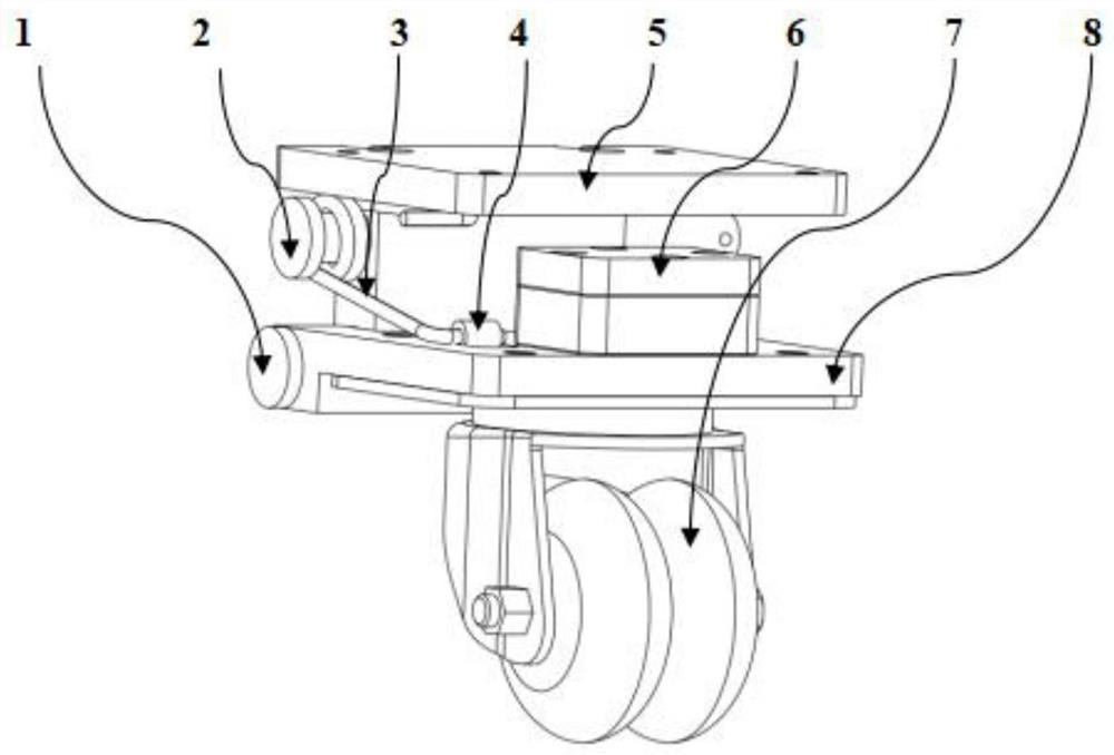
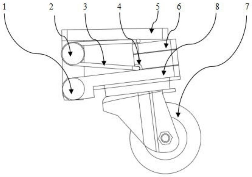
The invention discloses a driven wheel floating mechanism and an AGV. The driven wheel floating mechanism comprises a mounting plate, a floating plate, an elastic piece and a trundle. The floating plate and the mounting plate form a relative space below the mounting plate, one side of the floating plate is hinged to the mounting plate, and the other side of the floating plate freely rotates clockwise or anticlockwise with the hinge point as the axis so as to compress or release the relative space of the floating plate and the mounting plate. And the elastic piece is arranged in the relative space of the mounting plate and the floating plate. The trundles are installed below the floating plate. When the relative space of the elastic piece is changed, the elastic piece elastically deforms, so that the trundle always has vertically downward positive pressure. The AGV comprises a driving wheel and a driven wheel, and the driven wheel comprises any one of the driven wheel floating mechanisms. According to the floating wheel, no track is arranged, the needed installation space is small, the situation that floating cannot be achieved due to dead pinning cannot occur, the torsional spring is adopted as an elastic piece, the elasticity change range of the torsional spring is small, and the positive pressure of the floating wheel on the ground can be kept relatively constant.

Description

technical field [0001] The invention relates to the field of AGVs, in particular to a driven wheel floating mechanism and an AGV vehicle. Background technique [0002] At present, most of the driven wheel floating mechanisms on the market use linear guide rails and elastic elements to realize the floating design of the driven wheel. Because the space required by the linear guide is relatively large, it is difficult to meet the demand in the case of limited assembly space; and if the force received by the driven wheel is at a certain angle to the sliding direction of the linear guide, the linear guide will be stuck and cannot floating case. [0003] In addition, compression springs are generally used in cooperation with linear guide rails, and compression springs have relatively high requirements for installation space. If the installation space is small, the length of compression springs in the natural state is relatively short. According to the calculation formula of compr...

Claims


Application Information

Patent Timeline
Patent Type & Authority Applications(China)
IPC IPC(8): B60G11/18B60G11/00
CPCB60G11/18B60G11/00
Inventor 不公告发明人
Owner 广东塔斯克机器人有限公司
Why Eureka
Try Eureka