
Multifunctional projectile motion experiment demonstration instrument

A multi-functional, demonstrator technology, applied in the field of physical experiment demonstration models, can solve the problems of inability to capture motion trajectories and inability to obtain object motion trajectories intuitively, and achieve the effects of facilitating quantitative research, improving efficiency, and saving waste

Pending Publication Date: 2021-08-31
卓建银
View PDF10 Cites 1 Cited by
  • Summary
  • Abstract
  • Description
  • Claims
  • Application Information

AI Technical Summary

Problems solved by technology

[0005] However, this scheme cannot capture the trajectory of the motion, so students cannot intuitively obtain the difference in the trajectory of the object under the condition of controlling a single variable.

Method used


Image

  • Multifunctional projectile motion experiment demonstration instrument
  • Multifunctional projectile motion experiment demonstration instrument
  • Multifunctional projectile motion experiment demonstration instrument

Examples


Embodiment 1

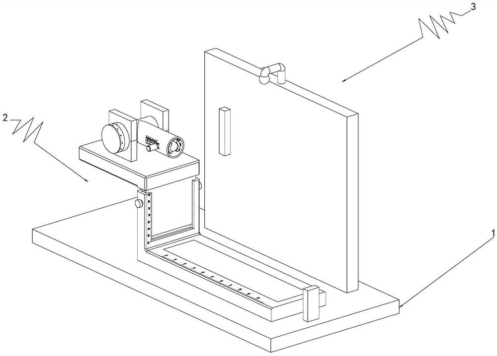
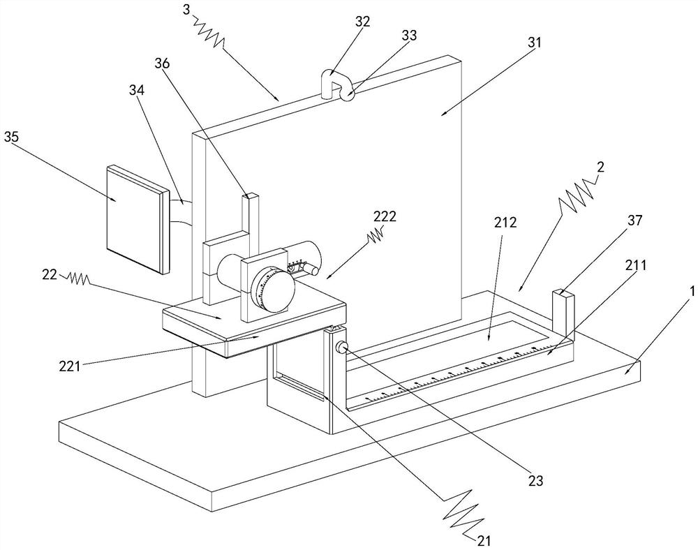
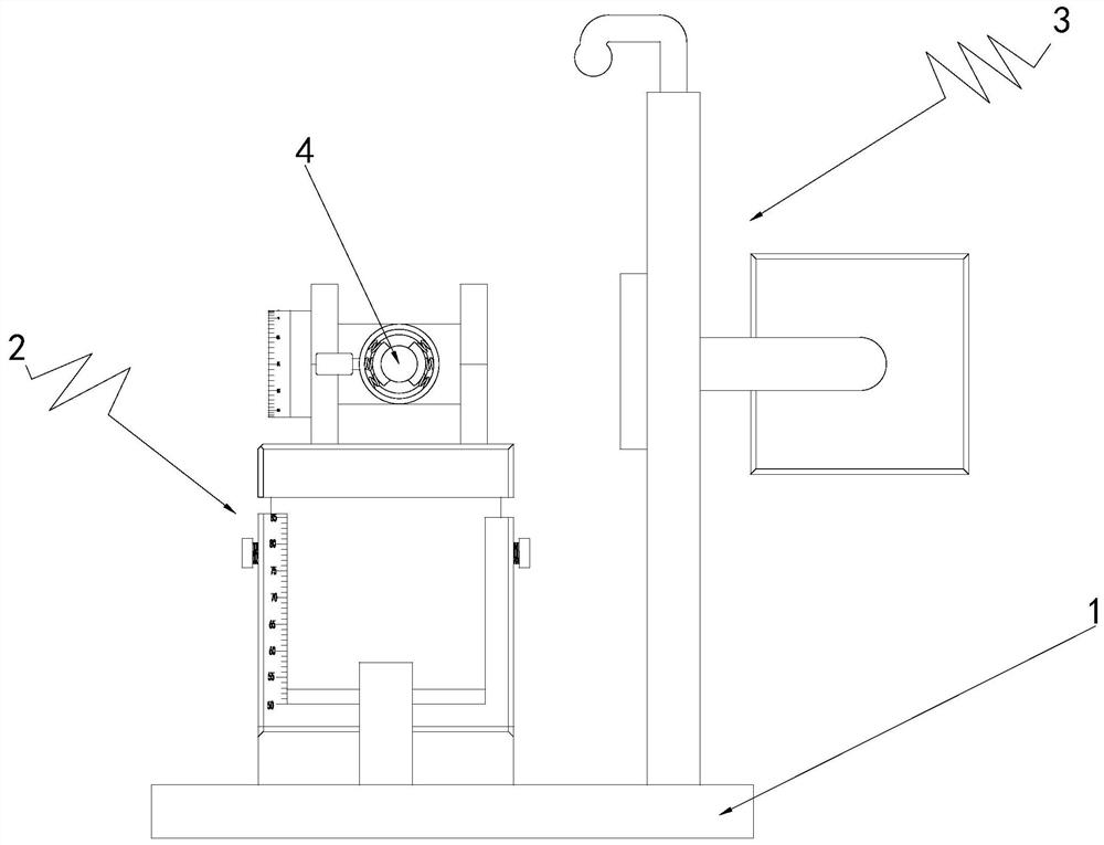
[0043] Such as Figure 2-3 As mentioned above, the teaching demonstration mechanism 2 has an angle adjustment part, which is used to demonstrate the physical flat throwing experiment when the angle adjustment part is at the zero scale line.

[0044] Such as figure 2 As shown, the teaching demonstration mechanism 2 includes a measuring part 21 , the measuring part 21 is arranged on the base 1 ; a demonstration part 22 , the demonstration part 22 is arranged on the measuring part 21 .

[0045] The measuring part 21 is used to measure the moving distance of the ball 4 in the horizontal direction during the flat throwing movement, and the demonstration part 22 is used to provide the ball 4 with an initial velocity in the horizontal direction, and then demonstrate the physical flat throwing experiment.

[0046] Such as Figure 7-9 As shown, the measuring component 21 includes an L-shaped connecting plate 211, the L-shaped connecting plate 211 has a horizontal portion and a verti...

Embodiment 2

[0061] This embodiment is the same as other content in the above-mentioned embodiment 1

[0062] When the angle adjusting member is located on a non-zero scale line, the teaching demonstration mechanism 2 is used to demonstrate a physical oblique throwing experiment.

[0063] When it is necessary to carry out the physical oblique throwing experiment, it is only necessary to rotate the adjusting disc 2224 counterclockwise (the direction in which the opening of the launching tube 2225 rotates obliquely upward), thereby changing the initial direction of motion of the ball 4, thereby performing the physical oblique throwing experiment, and The launch angle of the ball 4 can be recorded by observing the scale on the third scale line c facing the reference line, so that the oblique throwing experiment can be verified by the physical formula after the experiment is completed, and the angle range of the third scale line c is 0-60° is to make the physical oblique throwing experiment be...


PUM


Abstract

The invention relates to the technical field of physical experiment demonstration models, in particular to a multifunctional projectile motion experiment demonstration instrument. The multifunctional projectile motion experiment demonstration instrument comprises a base and an electronic display mechanism, wherein the base is provided with a teaching demonstration mechanism; and the electronic display mechanism is arranged on the base and located on one side of the teaching demonstration mechanism, and the electronic display mechanism is used for displaying the demonstration track of the teaching demonstration mechanism, so that students can more intuitively observe the motion trails of an object under different conditions and can compare different motion trails, the students can more deeply understand corresponding physical knowledge, and the teaching quality and effect are improved.

Description

technical field [0001] The invention relates to the technical field of physical experiment demonstration models, in particular to a multifunctional projectile motion experiment demonstration instrument. Background technique [0002] Experiment is a major branch of physics. In physics teaching, physics experiments have been running through elementary school, junior high school and even high school. In the teaching of physics experiments, especially when explaining the knowledge of projectile motion, teachers only rely on oral explanations. It is difficult to understand. Only through the teacher's on-site demonstration and the students' personal experiments can the students have a deep memory and a thorough understanding. This requires an intuitive and operable projectile kinematics demonstration device. [0003] Among the experimental equipment in the laboratory, most of the devices cannot directly obtain the trajectory of the projectile. There are problems such as unintuitiv...

Claims


Application Information

Patent Timeline
Patent Type & Authority Applications(China)
IPC IPC(8): G09B23/10
CPCG09B23/10
Inventor 卓建银许文龙郑春秋
Owner 卓建银
Learn More