Dewatering device for spunlace production line

A dehydration device and production line technology, applied in the direction of drying gas arrangement, progressive dryer, drying solid materials, etc., can solve problems such as not given, confused, unable to prompt negative pressure, etc., to achieve convenient manufacturing and assembly, and save space The effect of occupying and saving energy consumption

Active Publication Date: 2021-08-31
CHANGSHU FEILONG NON WOVEN MACHINERY
View PDF2 Cites 0 Cited by
  • Summary
  • Abstract
  • Description
  • Claims
  • Application Information

AI Technical Summary

Problems solved by technology

[0003] The technical information related to the dehydration device used in the spunlace production line can be seen in the published Chinese patent documents, typically such as the "water extraction device" recommended by the authorized announcement number CN107208343B. This patent has the effect of recovering waste heat, but has the following shortcomings: First, since the focus is on the internal mechanism of the hot air diffusion box, no technology is given to enable the spunlace non-woven fabric (the patent is called "non-woven fabric") to pass through the negative pressure suction box smoothly with the assistance of the conveyor belt Enlightenment; secondly, it can be determined from the accompanying drawings of the patent specification and the content of the specification that the aforementioned negative pressure suction box is in the form of a single box configuration, so the dehydration effect of non-woven fabrics with a large grammage will be affected to a certain extent. Of course, there will be no Slowing down the moving speed of the spun fabric can improve the dehydration effect to a certain extent, but the production capacity per unit time, that is, the working efficiency of spunlace will be affected; Negative pressure and the negative pressure of the negative pressure suction box cannot be adjusted on-line as needed, thus causing inconvenience or even blindness in the actual production process; The respective positions of parts such as cloth guide rollers and screen curtains and the reasonable cooperation relationship between them make the formation of a complete dehydration device somewhat confusing; fifth, according to the patent specification, especially the claims of the patent From the summary of 1, it can be seen that the structure of the whole hot air diffusion box is relatively complicated and because the recycled hot air needs to pass through metal plate elements, fine metal mesh and perforated metal plate elements in order to be led to the negative pressure water suction box, the hot air resistance is large However, the power of the vacuum pump must be increased accordingly, which is not conducive to saving energy consumption.

Method used


Image

  • Dewatering device for spunlace production line
  • Dewatering device for spunlace production line
  • Dewatering device for spunlace production line

Examples


Embodiment Construction

[0019] In order to understand the technical essence and beneficial effects of the present invention more clearly, the applicant will describe in detail the following examples, but the descriptions of the examples are not intended to limit the solutions of the present invention. Equivalent transformations that are only formal but not substantive should be regarded as the scope of the technical solution of the present invention.

[0020] In the following descriptions, all concepts related to directionality or orientation of up, down, left, right, front and back are based on figure 1 The current position is a reference, so it cannot be understood as a special limitation on the technical solution provided by the present invention.

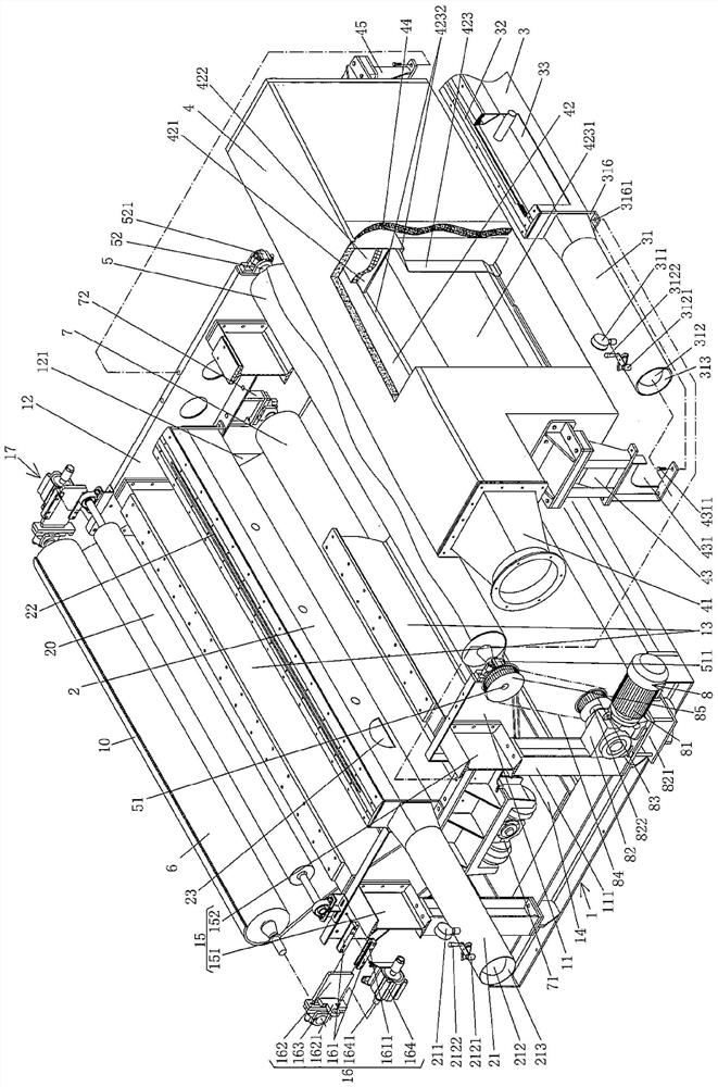
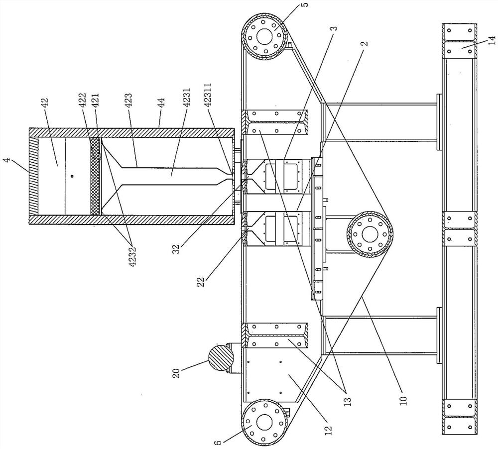
[0021] See figure 1 and combine figure 2 , shows a frame 1, and this frame 1 is supported on the ground under the state of use, and this frame 1 is made up of frame front support 11, frame rear support 12, support beam 13 and frame on the frame The...


PUM


Abstract

The invention discloses a dewatering device for a spunlace production line. The device comprises a rack which is composed of a rack front support, a rack rear support, a rack upper supporting beam and a rack lower supporting beam, a left negative-pressure water suction box, a right negative-pressure water suction box, a hot air diffusion box, a supporting net curtain driving roller, a supporting net curtain driven roller, a supporting net curtain deviation rectifying roller, a supporting net curtain driving roller driving mechanism and a supporting net curtain. The front end of the left negative-pressure water suction box is fixed with the rack front support, the rear end of the left negative-pressure water suction box is closed, and the upper part of the left negative-pressure water suction box is provided with a left negative-pressure water suction box water suction port; the front end of the right negative-pressure water suction box is fixed with the rack front support, the rear end of the right negative-pressure water suction box is closed, and the upper part of the right negative-pressure water suction box is provided with a right negative-pressure water suction box water suction port; the lower portion of the front end of the hot air diffusion box is borne on the front end of the right negative-pressure water suction box, the rear end is fixed with the rack rear support, a mesh plate is arranged in a cavity of the hot air diffusion box, and a hot air uniform diffusion filter screen pad is arranged on the mesh plate; the supporting net curtain driving roller is arranged on the upper portions of the rack front support and the rack rear support, the supporting net curtain driven roller is arranged between the upper portions of the rack front support and the rack rear support, and the supporting net curtain deviation rectifying roller is arranged between the lower portions of the rack front support and the rack rear support; the supporting net curtain driving roller driving mechanism is arranged at the front side of the rack front support; and the supporting net curtain sleeves supporting net curtain driving roller, the supporting net curtain driven roller and the supporting net curtain deviation rectifying roller. The good dewatering requirement on a spunlace non-woven product with large gram weight is met.

Description

technical field [0001] The invention belongs to the technical field of non-woven machinery, and in particular relates to a dewatering device for a spunlace production line. Background technique [0002] As known in the industry, the spunlace non-woven production line, that is, the spunlace production line, is usually equipped with a dehydration device, and the dehydration method generally adopts a vacuum or negative pressure method. The non-woven products from the spunlace machine, such as spunlace non-woven fabric or felt It is dehydrated by the dehydration device, and then enters the drying process for drying (also called "drying"). [0003] The technical information related to the dehydration device used in the spunlace production line can be seen in the published Chinese patent documents, typically such as the "water extraction device" recommended by the authorized announcement number CN107208343B. This patent has the effect of recovering waste heat, but has the followin...

Claims


Application Information

Patent Timeline
IPC IPC(8): F26B13/08F26B13/14F26B21/00F26B21/06F26B25/02F26B25/00
CPCF26B13/08F26B13/14F26B21/001F26B21/06F26B25/02F26B25/00Y02P70/10
Inventor 韩雪龙韩一斌徐志高朱志建
Owner CHANGSHU FEILONG NON WOVEN MACHINERY
Why Eureka
Try Eureka