Beam forming method of compact planar array Massive MIMO system

A beamforming method and planar array technology, applied in transmission systems, radio transmission systems, diversity/multi-antenna systems, etc., can solve the problems of sparse channels, high complexity, and inappropriate deployment of high-frequency Massive MIMO systems. User and rate, effect of guaranteed robustness

Active Publication Date: 2021-08-27
广州市埃特斯通讯设备有限公司
View PDF4 Cites 5 Cited by
  • Summary
  • Abstract
  • Description
  • Claims
  • Application Information

AI Technical Summary

Problems solved by technology

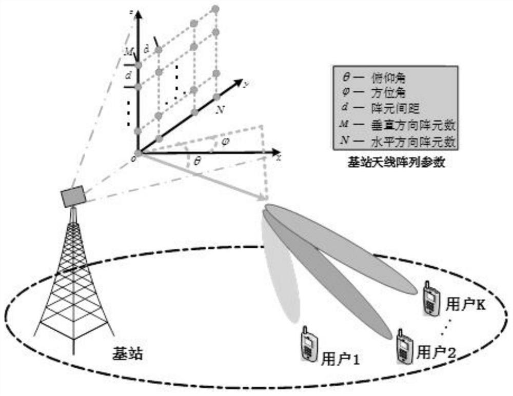
[0002] In terms of signal propagation characteristics and antenna array structure, the high-band Massive MIMO system is different from the traditional low-frequency multi-antenna system: on the one hand, the path loss of high-frequency communication is more significant, the channel is sparser, and the main transmission method is LOS transmission; On the other hand, the traditional ULA architecture is no longer applicable, and a compact planar antenna array is a more suitable deployment method, but the dense deployment of antennas will cause non-negligible mutual coupling damage
[0003] Most beamforming methods in the prior art do not take into account the mutual coupling effect caused by the dense deployment of base station antennas, and are not suitable for high-band Massive MIMO systems that deploy compact planar antenna arrays
However, the existing beamforming design methods that consider the mutual coupling between array elements do not make full use of the asymptotic / steady-state advantages of Massive MIMO technology due to the significant increase in the size of the antenna array, which makes the existing beamforming methods complicated. High accuracy, not suitable for high-band Massive MIMO systems

Method used


Image

  • Beam forming method of compact planar array Massive MIMO system
  • Beam forming method of compact planar array Massive MIMO system
  • Beam forming method of compact planar array Massive MIMO system

Examples


Embodiment Construction

[0055] The present invention will be described in detail below in conjunction with the accompanying drawings and specific embodiments.

[0056] Compared with the traditional low-frequency signal, the high-frequency signal has a shorter wavelength. When using it for wireless data transmission, it can achieve a smaller physical size of the antenna, which is more conducive to the integration of the antenna, so that high-frequency Communication and Massive MIMO are well integrated.

[0057] In order to better integrate the performance advantages of high-frequency communication and Massive MIMO technologies, while compensating for transmission path loss and mutual coupling damage, beamforming becomes particularly urgent and important. By using effective beamforming preprocessing, the system changes the weighting coefficients of the antenna array elements at the transmitting end, optimizes the radiation direction of the antenna, and then gathers the energy of the received signal to ...


PUM


Abstract

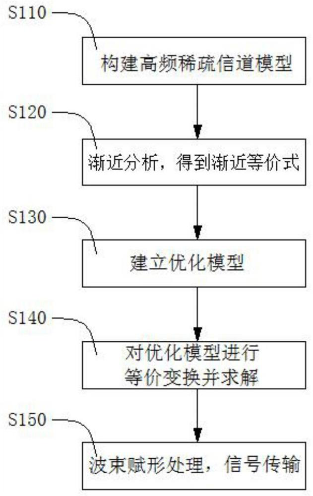
The invention discloses a beam forming method for a compact planar array Massive MIMO system. The beam forming method comprises the following steps: constructing a high-frequency sparse channel model on the basis of not considering a mutual coupling effect; performing asymptotic analysis on the high-frequency sparse channel model to obtain an asymptotic equivalence formula of a channel correlation matrix; based on an asymptotic equivalence formula, establishing an optimization model by taking maximization of the minimum receiving SINR values of all users as a target; carrying out equivalent transformation and solving on the optimization model to obtain a beam forming weight vector; based on the beamforming weight vector, performing beamforming processing on the user data, and performing signal transmission. According to the method, an asymptotic equivalence formula of a channel correlation matrix is derived through asymptotic analysis of a high-frequency sparse channel, and on the basis, a beamforming optimization problem is established by taking maximization of a user receiving signal to interference plus noise ratio as a target, so that the robustness of system performance to mutual coupling damage is ensured while the user sum rate is improved.

Description

technical field [0001] The invention belongs to the technical field of mobile communication, and in particular relates to a beam forming method of a compact planar array Massive MIMO system. Background technique [0002] In terms of signal propagation characteristics and antenna array structure, the high-band Massive MIMO system is different from the traditional low-frequency multi-antenna system: on the one hand, the path loss of high-frequency communication is more significant, the channel is sparser, and the main transmission method is LOS transmission; On the other hand, the traditional ULA architecture is no longer applicable, and a compact planar antenna array is a more suitable deployment method, but the dense deployment of antennas will cause non-negligible mutual coupling damage. [0003] Most beamforming methods in the prior art do not take into account the mutual coupling effect caused by the dense deployment of base station antennas, and are not suitable for high...

Claims


Application Information

Patent Timeline
Patent Type & Authority Applications(China)
IPC IPC(8): H04B7/06H04B7/08
CPCH04B7/0617H04B7/086
Inventor 张阳赵梦琼庞立华张舒婷
Owner 广州市埃特斯通讯设备有限公司
Why Eureka
Try Eureka