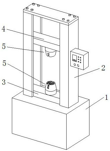
A metal material plastic yield strength testing device
A technology of plastic yielding and strength detection, applied in measuring devices, using stable tension/pressure to test the strength of materials, analyzing materials, etc., can solve the problems of limited contact area, loose clamping position, inaccurate results, etc. Hold firmly, avoid loosening, ensure the effect of accuracy
- Summary
- Abstract
- Description
- Claims
- Application Information
AI Technical Summary
Problems solved by technology
Method used
Image
Examples
Embodiment example 1
[0036] see Figure 1-4, a metal material plastic yield strength detection device, comprising a testing machine main body 1, the lower end of the bracket 2 of the testing machine main body 1 is installed with a lower beam 3, the upper end of the bracket 2 is provided with a lifting upper beam 4, the lower beam 4 The middle position of the upper surface of 3 and the middle position of the lower surface of the lifting upper beam 4 are fixedly installed with a chuck mechanism 5, and the chuck mechanism 5 includes an outer casing 6, and both side walls of the upper end of the outer casing 6 are provided with. Mounting port 7, the upper end of the inner wall of the outer casing 6 is uniformly provided with a plurality of sliding rails 8 in a circumference, and sliding sector-shaped clamping blocks 9 are slidably installed on the sliding rails 8. The lower end of the inner end of the sliding sector-shaped clamping block 9 A fan-shaped groove 10 is provided in each of them, a vertical...
Embodiment example 2
[0043] see Figure 4 , 8 and 9, the synchronous lifting mechanism 13 includes a first support rod 16 that is fixed horizontally and fixedly installed on the lower end of the inner wall of the outer casing 6 and has the same number as the sliding sector clamping block 9. The inner end of the first support rod 16 is slidably installed with Vertically arranged lifting rods 17, the top ends of the lifting rods 17 are rotatably installed with double-sided rollers 18 that are rolled inside the lower end of the sliding sector clamping block 9, and the lower ends of the lifting rods 17 are provided with annular teeth 19, The lower ends of the lift rods 17 are all engaged with transmission rods 20 , and the inner parts of both ends of the transmission rod 20 are installed on the lower end of the inner wall of the outer casing 6 through second support rods 21 .
[0044] The servo motor 26 of the synchronous lifting mechanism 13 can drive one of the transmission rods 20 to rotate throug...
PUM
 Abstract
Description
Claims
Application Information
 - R&D
- Intellectual Property
- Life Sciences
- Materials
- Tech Scout
- Unparalleled Data Quality
- Higher Quality Content
- 60% Fewer Hallucinations
Browse by: Latest US Patents, China's latest patents, Technical Efficacy Thesaurus, Application Domain, Technology Topic, Popular Technical Reports.
© 2025 PatSnap. All rights reserved.Legal|Privacy policy|Modern Slavery Act Transparency Statement|Sitemap|About US| Contact US: help@patsnap.com


