Eureka AIR delivers breakthrough ideas for toughest innovation challenges, trusted by R&D personnel around the world.

A semi-active vibration-absorbing and energy-dissipating control system for suppressing bridge vortex-induced vibration

A control system, vortex-induced vibration technology, applied in bridges, bridge parts, bridge construction and other directions, can solve the problems of low vertical bending vortex vibration frequency of bridges, reduced applicability, large mass, etc., to reduce the weight of the mass body and reduce the spring Quality and cost, the effect of the small size of the device

Active Publication Date: 2022-03-04
DALIAN UNIV OF TECH
View PDF11 Cites 0 Cited by
  • Summary
  • Abstract
  • Description
  • Claims
  • Application Information

AI Technical Summary

Problems solved by technology

Tuned mass dampers can be used to control the vibration of bridges. However, the vertical bending vortex frequency of bridges is low (<0.2Hz, even lower than 0.1Hz), so the use of tuned mass dampers requires spring stretching or compression lengths of several meters or even dozens m, the lower the frequency, the smaller the corresponding system stiffness, the longer the spring required (squared with the vibration period), the greater the mass, the higher the cost
On the one hand, it is difficult to install directly inside the main girder. On the other hand, if traditional metal springs are used, their mass will be very large, reaching tens of tons or even greater, and their applicability will be greatly reduced.
Therefore, the existing traditional tuned mass dampers are generally only used in occasions where the vibration frequency is higher than 0.2Hz

Method used

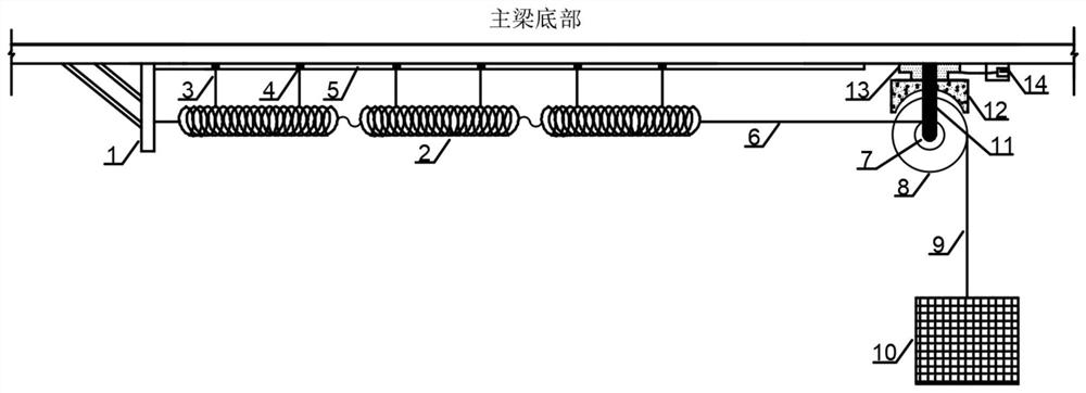

Image

  • A semi-active vibration-absorbing and energy-dissipating control system for suppressing bridge vortex-induced vibration
  • A semi-active vibration-absorbing and energy-dissipating control system for suppressing bridge vortex-induced vibration

Examples


Embodiment Construction

[0028] Below in conjunction with technical scheme and accompanying drawing, describe the specific embodiment of the present invention in detail, but the embodiment of the present invention is not limited thereto:

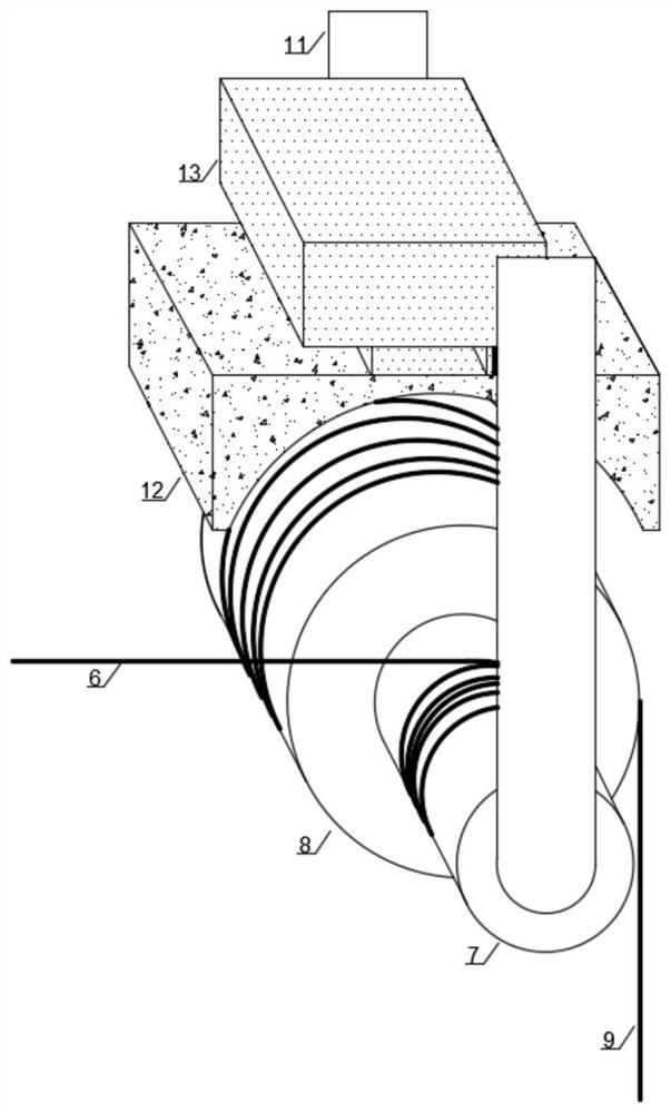
[0029] Such as figure 1 As shown, a semi-active vibration-absorbing and energy-dissipating control system for suppressing vortex-induced vibration of a long-span bridge includes a spring end plate 1 fixed on the bottom plate of the main girder, a linear tension spring 2, a vertical suspension rope 3, a slider 4, a slider Road 5, first high-strength rope 6, first pulley 7, second pulley 8, second high-strength rope 9, mass body 10, pulley fixing device 11, energy dissipation device 12, electric control jack 13, controller 14; spring end The plate 1 is usually set on the bottom of the main girder or on the pier (tower, platform), and can be made of a stiffened steel plate, which is used to fix one or several linear tension springs 2 arranged in series or in parallel; ...


PUM


Abstract

The invention belongs to the technical field of wind-induced vibration control of bridges, and provides a semi-active vibration-absorbing and energy-dissipating control system for suppressing vortex-induced vibration of bridges. Compared with the traditional tuned mass damping system, its advantages and characteristics: (1) The spring is placed horizontally at the bottom of the beam, and the length Unrestricted, it can meet the low-frequency target frequency requirements; (2) Multiple series and parallel springs can be combined in different ways to achieve different target frequencies to meet the multi-order eddy vibration control requirements; (3) Fiber-reinforced nylon material springs are used, and the The spring is slotted, which can greatly expand the range of frequency implementation; (4) The material and form of the mass body are not limited, and water bags can be used, which is low in cost and easy to disassemble and adjust; (5) Coaxial pulleys with different diameters can be used. Significantly improve the high-frequency vibration control efficiency; (6) The vibration of the mass body is controlled by human semi-automatic intervention to achieve higher control efficiency; (7) The device is small in size and installed at the bottom of the beam, which basically does not affect the appearance; (8) The project cost is greatly increased reduce.

Description

technical field [0001] The invention belongs to the technical field of wind-induced vibration control of bridges, and relates to a semi-active vibration-absorbing and energy-dissipating control system for suppressing vortex-induced vibration of bridges. Background technique [0002] Vortex-induced vibration of long-span bridges (referred to as vortex vibration) occurs from time to time, causing adverse effects on the bridge structure itself and the drivers and passengers on the bridge, and even causing social panic, so it is necessary to prevent and control it. Long-span bridges generally experience vertical bending vortex vibration, and torsional vortex vibration rarely occurs. Moreover, even if there is torsional vortex vibration, the amplitude is generally small, and the problem is not serious. Tuned mass dampers can be used to control the vibration of bridges. However, the vertical bending vortex vibration frequency of bridges is low (<0.2Hz, even lower than 0.1Hz). ...

Claims


Application Information

Patent Timeline
Patent Type & Authority Patents(China)
IPC IPC(8): F16F15/067F16F15/04F16F15/02F16F15/28E01D19/00
CPCF16F15/067F16F15/04F16F15/02F16F15/28E01D19/00
Inventor 许福友朱巍志王博李文杰刘高
Owner DALIAN UNIV OF TECH
Why Eureka
Eureka Blog
Learn More