
Automatic welding equipment for power transmission iron tower

An automatic welding and power transmission technology, applied in welding equipment, laser welding equipment, metal processing equipment, etc., can solve the problems of poor welding strength, uneven distribution of welding spots, and large labor consumption.

Inactive Publication Date: 2021-08-27
SHANDONG LUNENG TAISHAN TOWER
View PDF0 Cites 0 Cited by
  • Summary
  • Abstract
  • Description
  • Claims
  • Application Information

AI Technical Summary

Problems solved by technology

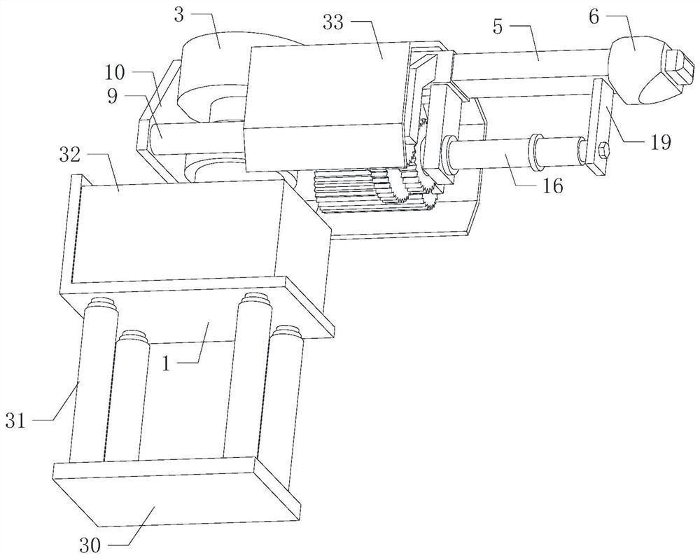
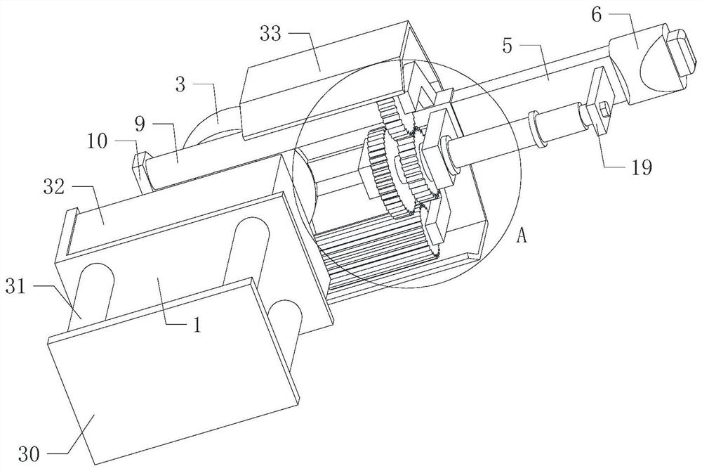
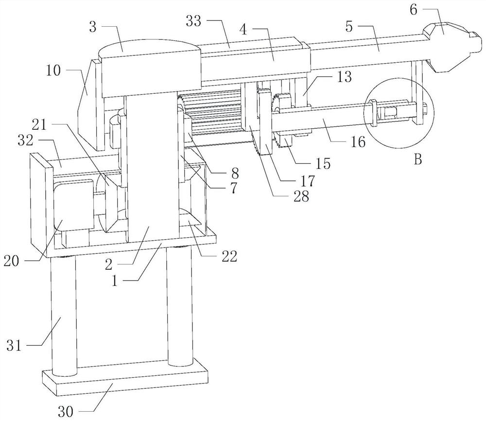
[0002] As we all know, the power transmission tower is the main equipment for erecting the power grid. It can keep the power grid away from the ground and avoid the harm of the power grid to the human body. The iron tower is usually welded by metal frames. The existing welding methods usually use manual welding. Manual welding The operation method is relatively cumbersome, the time required for welding is long, the work efficiency is low, and the manpower consumption is large. At the same time, the welding strength is poor and the distribution of solder joints is uneven, resulting in low strength of the iron tower and affecting its production quality.

Method used


Image

  • Automatic welding equipment for power transmission iron tower
  • Automatic welding equipment for power transmission iron tower
  • Automatic welding equipment for power transmission iron tower

Examples


Embodiment Construction

[0032] The following will clearly and completely describe the technical solutions in the embodiments of the present invention with reference to the accompanying drawings in the embodiments of the present invention. Obviously, the described embodiments are only some, not all, embodiments of the present invention.

[0033] In the description of the present invention, it should be noted that the terms belonging to "center", "upper", "lower", "left", "right", "vertical", "horizontal", "inner", "outer" etc. The indicated orientation or positional relationship is based on the orientation or positional relationship shown in the drawings, and is only for the convenience of describing the present invention and simplifying the description, rather than indicating or implying that the referred device or element must have a specific orientation, or in a specific orientation. construction and operation, therefore, should not be construed as limiting the invention.

[0034] In the descriptio...


PUM


Abstract

The invention relates to the technical field of welding equipment, in particular to automatic welding equipment for a power transmission iron tower. The automatic welding equipment comprises a right-angle frame and a rotating shaft, wherein a lifting mechanism is arranged at the bottom of the right-angle frame, and the lifting mechanism is used for pushing the right-angle frame to move; and the rotating shaft is rotationally installed on the right-angle frame, a power mechanism is arranged on the right-angle frame and used for driving the rotating shaft to rotate, a top disc is arranged at the top of the rotating shaft, and a square sliding sleeve is transversely arranged on the circumferential side wall of the top disc. According to the equipment, automatic welding treatment on the iron tower can be achieved, the welding mode is effectively simplified, time and labor are saved, meanwhile, welding spot distribution uniformity is improved, welding strength is effectively improved, and practicability is improved.

Description

technical field [0001] The invention relates to the technical field of welding equipment, in particular to an automatic welding equipment for a power transmission iron tower. Background technique [0002] As we all know, the power transmission tower is the main equipment for erecting the power grid. It can keep the power grid away from the ground and avoid the harm of the power grid to the human body. The iron tower is usually welded by metal frames. The existing welding methods usually use manual welding. Manual welding The operation method is relatively cumbersome, the time required for welding is long, the work efficiency is low, and the manpower consumption is large. At the same time, the welding strength is poor and the distribution of solder joints is uneven, resulting in low strength of the iron tower and affecting its production quality. Contents of the invention [0003] In order to solve the above technical problems, the present invention provides an automatic we...

Claims


Application Information

Patent Timeline
IPC IPC(8): B23K26/21B23K26/08B23K26/70
CPCB23K26/0876B23K26/21B23K26/702B23K26/706
Inventor 郭连军马国亮李庆森张全富
Owner SHANDONG LUNENG TAISHAN TOWER
Learn More