
Mechanical gear cleaning device and operation method thereof

A technology for cleaning devices and gears, applied in cleaning methods and appliances, cleaning methods using tools, cleaning methods using liquids, etc., can solve problems such as difficult stain cleaning, insufficient cleaning, and a lot of time-consuming, so as to avoid insufficient Thoroughness, improving convenience, and improving the effect of cleaning diversity

Inactive Publication Date: 2021-08-27
WENZHOU POLYTECHNIC
View PDF7 Cites 4 Cited by
  • Summary
  • Abstract
  • Description
  • Claims
  • Application Information

AI Technical Summary

Problems solved by technology

[0004] The purpose of the present invention is to provide a mechanical gear cleaning device and its operating method to solve the problem that the front and back sides of the gear cannot be cleaned in batches at the same time, and the cleaning efficiency of a single gear is too low. There will be a lot of stains remaining in the gaps between the teeth. It is difficult to clean the stains in the prior art, the cleaning process takes a lot of time, and the cleaning is not thorough enough.

Method used


Image

  • Mechanical gear cleaning device and operation method thereof
  • Mechanical gear cleaning device and operation method thereof
  • Mechanical gear cleaning device and operation method thereof

Examples


Embodiment 1

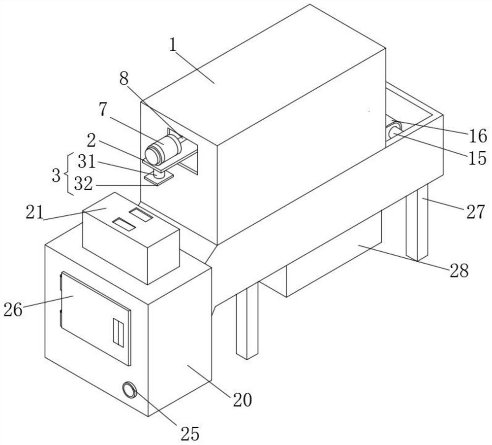
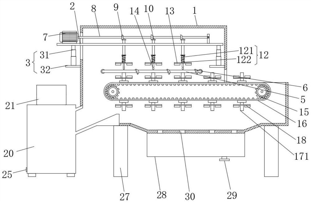
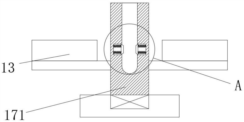
[0037] Such as Figure 1-7As shown, the present invention provides a technical solution: a mechanical gear cleaning device, including a cleaning box 1, one side of the cleaning box 1 is slidingly connected with a lifting plate 2, and both sides of the bottom of the lifting plate 2 are bolted with a lifting mechanism 3 The vertical movement of the lifting plate 2 is driven by the lifting mechanism 3, which effectively improves the role of the device to fix the gears to be cleaned. A flushing mechanism 4 is installed on the back of the cleaning box 1, and one end of the flushing mechanism 4 is connected to a water outlet pipe 5. And the front of the water outlet pipe 5 is connected with a nozzle 6, and the gear to be cleaned is washed by the flushing mechanism 4, which effectively improves the multi-directional cleaning effect of the device to be cleaned. The top of the lifting plate 2 is bolted with a first motor 7, and The output end of the first motor 7 is bolted with a rotat...

Embodiment 2

[0039] Such as Figure 1-7 As shown, the present invention provides a technical solution: a mechanical gear cleaning device, including a cleaning box 1, one side of the cleaning box 1 is slidingly connected with a lifting plate 2, and both sides of the bottom of the lifting plate 2 are bolted with a lifting mechanism 3 The vertical movement of the lifting plate 2 is driven by the lifting mechanism 3, which effectively improves the role of the device to fix the gears to be cleaned. A flushing mechanism 4 is installed on the back of the cleaning box 1, and one end of the flushing mechanism 4 is connected to a water outlet pipe 5. And the front of the water outlet pipe 5 is connected with a nozzle 6, and the gear to be cleaned is washed by the flushing mechanism 4, which effectively improves the multi-directional cleaning effect of the device to be cleaned. The top of the lifting plate 2 is bolted with a first motor 7, and The output end of the first motor 7 is bolted with a rota...


PUM


Abstract

The invention discloses a mechanical gear cleaning device and an operation method thereof. The mechanical gear cleaning device comprises a cleaning box, one side of the cleaning box is slidably connected with a lifting plate, and the two sides of the bottom of the lifting plate are in bolted connection with lifting mechanisms. To-be-cleaned gears are placed on the surface of a cylinder, the lifting mechanisms are started to drive a guide pipe at the bottom of an upper cleaning plate to be fixed to a clamping mechanism, a first motor is started to drive a rotating rod to rotate, and the rotating rod drives a second bevel gear to rotate through a first bevel gear, so that the rotating rod drives a clamped mechanism to rotate; the upper cleaning plate and a lower cleaning plate are used for washing the surfaces of the gears, so that incomplete cleaning is avoided, and the cleaning diversity is improved; and a washing mechanism is started to wash the gears, a second motor is started, the second motor drives a roller to rotate, the roller drives a conveying belt to move, the multiple gears on the conveying belt are cleaned, and therefore the multiple gears can be cleaned together, and convenience is improved.

Description

technical field [0001] The invention relates to the technical field of gear cleaning, in particular to a mechanical gear cleaning device and an operating method thereof. Background technique [0002] A gear is a mechanical element with gears on the rim that continuously mesh to transmit motion and power. The application of gears in transmission has appeared very early. At the end of the 19th century, the principle of generative gear cutting method and special machine tools and cutting tools using this principle appeared one after another. With the development of production, the stability of gear operation was paid more attention. The surface on which the gear teeth are located and the method of manufacturing are classified. The tooth shape of the gear includes tooth profile curve, pressure angle, tooth height and displacement. Involute gears are relatively easy to manufacture, so among the gears used in modern times, involute gears account for the absolute majority, while...

Claims


Application Information

Patent Timeline
Patent Type & Authority Applications(China)
IPC IPC(8): B08B1/00B08B1/02B08B3/02B08B13/00F26B21/00
CPCB08B3/022B08B13/00F26B21/001F26B21/004B08B1/12B08B1/20
Inventor 张洁徐诚角王伯旺温正荣刘长江林潘忠
Owner WENZHOU POLYTECHNIC
Learn More