Steam circulation confluence energy-saving system

An energy-saving system, steam technology, applied in pipeline systems, chemical/physical/physicochemical processes, chemical instruments and methods, etc., can solve problems affecting heat exchange capacity, corrosion of steam equipment, low steam flow rate of heat exchangers, etc., to achieve The effect of controlling the intake pressure, reducing the waste of heat energy and increasing the steam flow rate

Inactive Publication Date: 2021-08-27
山东省昌邑石化有限公司
View PDF0 Cites 0 Cited by
  • Summary
  • Abstract
  • Description
  • Claims
  • Application Information

AI Technical Summary

Problems solved by technology

[0003] Among them, the opening of the above-mentioned regulating valve is generally adjusted manually, and the self-control is not fully realized. After the steam is throttled and decompressed by the valve, it is supplied to the heat exchanger, and the high-pressure (high-grade) steam is throttled and decompressed to the pressure required for production ( There is depreciation and loss of steam energy in the process of low grade)
Since the self-control is not fully realized, it often relies on the experience of the operator for control, which can easily cause the steam consumption to not be adjusted in real time according to the load, which is not conducive to production stability and leads to excessive energy consumption
[0004] The internal steam flow rate of the above-mentioned heat exchanger is low, the water film is thick, the heat transfer coefficient is low, and the heat transfer capacity is low; in addition, non-condensable gases (air and carbon dioxide) will be generated in the steam system, according to industry experimental data: 0.5 % volume of air mixed into the steam, the heat transfer coefficient of the equipment will drop by about half
Non-condensable gas not only affects the heat transfer capacity, but also corrodes the steam equipment and affects the life of the equipment
[0005] The thermal energy utilization rate of the above steam traps is low, and the waste heat of condensed water is not recycled, which wastes heat energy

Method used


Image

  • Steam circulation confluence energy-saving system
  • Steam circulation confluence energy-saving system
  • Steam circulation confluence energy-saving system

Examples


Embodiment Construction

[0031] In order to make the technical means, creative features, goals and effects achieved by the present invention easy to understand, the present invention will be further described below in conjunction with specific embodiments.

[0032] In the description of the present invention, it should be noted that the terms "upper", "lower", "inner", "outer", "front end", "rear end", "both ends", "one end", "another end" The orientation or positional relationship indicated by etc. is based on the orientation or positional relationship shown in the drawings, which is only for the convenience of describing the present invention and simplifying the description, rather than indicating or implying that the referred device or element must have a specific orientation, use a specific Azimuth configuration and operation, therefore, should not be construed as limiting the invention. In addition, the terms "first" and "second" are used for descriptive purposes only, and should not be understoo...


PUM


Abstract

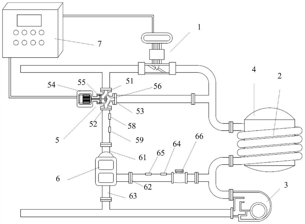
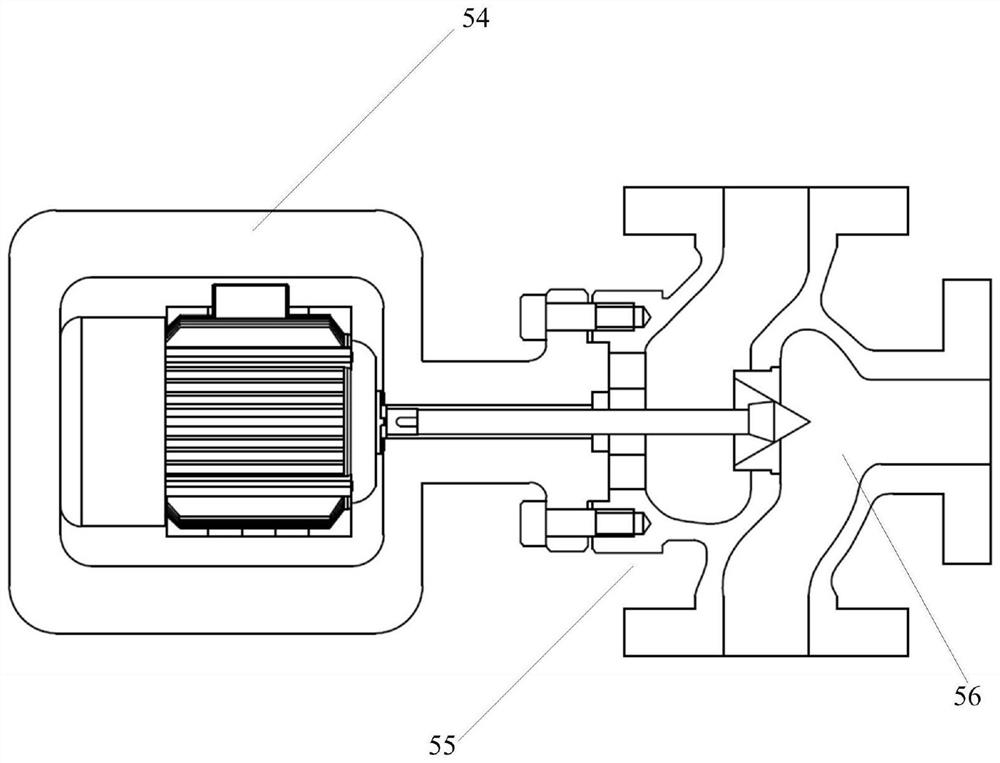
The invention discloses a steam circulation confluence energy-saving system which is characterized in that a cyclone device and a steam-water separator are additionally arranged on the basis of an original system; the cyclone device and a regulating valve are mounted in parallel; a steam inlet of the cyclone device is communicated with a pipeline between the inlet end of the regulating valve and a high-pressure steam source, and an air suction inlet of the cyclone device is communicated with an exhaust outlet of the steam-water separator; a confluence outlet of the cyclone device is communicated with a pipeline between the regulating valve and a surrounding device/reboiler; an inlet of the steam-water separator is communicated with a pipeline between the surrounding device/reboiler and a drain valve; and a water outlet of the steam-water separator is communicated with a water drainage pipeline of the drain valve. The cyclone device and the adjusting valve are installed in parallel, transformation is easy, and the improvement cost is low. The flow rate of steam in a heat exchanger can be increased, the thickness of a water film is reduced, the heat transfer coefficient of the heat exchanger is improved, the steam can be fully and reasonably used in grade and quantity, the air inlet pressure of the heat exchanger can be effectively controlled, and energy loss is reduced.

Description

technical field [0001] The invention belongs to the technical field of energy-saving and environment-friendly equipment, and in particular relates to a steam cycle confluence energy-saving system. Background technique [0002] At present, the steam heating system is widely used in air separation equipment, petrochemical industry, food industry, and metallurgical industry. It mainly uses the heat released by steam to heat the required process gas. A common steam heating system is generally composed of a regulating valve, a surround / reboiler, a steam trap and connected pipelines. [0003] Among them, the opening of the above-mentioned regulating valve is generally adjusted manually, and the self-control is not fully realized. After the steam is throttled and decompressed by the valve, it is supplied to the heat exchanger, and the high-pressure (high-grade) steam is throttled and decompressed to the pressure required for production ( There is depreciation and loss of steam ene...

Claims


Application Information

Patent Timeline
Patent Type & Authority Applications(China)
IPC IPC(8): B01J19/00F17D1/04F17D3/01
CPCB01J19/00B01J2219/00087F17D1/04F17D3/01
Inventor 任培杰王明传王存金夏鲁北蔡超
Owner 山东省昌邑石化有限公司
Why Eureka
Try Eureka