
Thermocouple connection structure with impact protection function

A connection structure and protection function technology, applied in the field of thermocouple connection structure, can solve problems such as thermocouple damage, and achieve the effect of reducing the probability of damage

Active Publication Date: 2021-08-24
安徽福特控制系统有限公司
View PDF5 Cites 0 Cited by
  • Summary
  • Abstract
  • Description
  • Claims
  • Application Information

AI Technical Summary

Problems solved by technology

[0003] Thermocouples are sometimes installed in vibration containers. Existing thermocouples are usually installed and fixed by components such as fixing brackets or clamps. This installation method has disadvantages. First, this installation method will directly expose the thermocouples. Outside the installation structure, thermocouples are more likely to be damaged by external shocks. Secondly, when the container vibrates, the thermocouples will vibrate together. There is a possibility of thermocouples being damaged due to vibrations. In addition, thermocouples are usually connected by data lines. The cable usually has some length reserved, and the existing processing method is to bundle the cable into a roll and fix it on the outside of the container, so an additional bundle component is required to fix it

Method used


Image

  • Thermocouple connection structure with impact protection function
  • Thermocouple connection structure with impact protection function
  • Thermocouple connection structure with impact protection function

Examples


Embodiment Construction

[0028] The following will clearly and completely describe the technical solutions in the embodiments of the present invention with reference to the accompanying drawings in the embodiments of the present invention. Obviously, the described embodiments are only some, not all, embodiments of the present invention. Based on the embodiments of the present invention, all other embodiments obtained by persons of ordinary skill in the art without making creative efforts belong to the protection scope of the present invention.

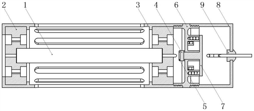
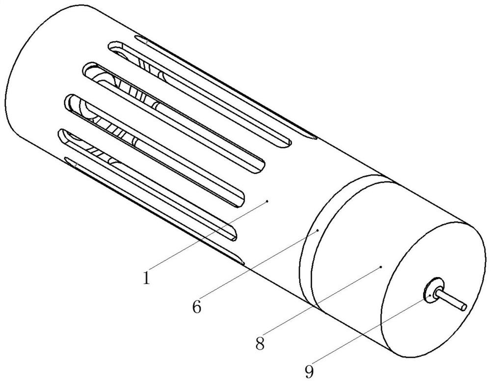
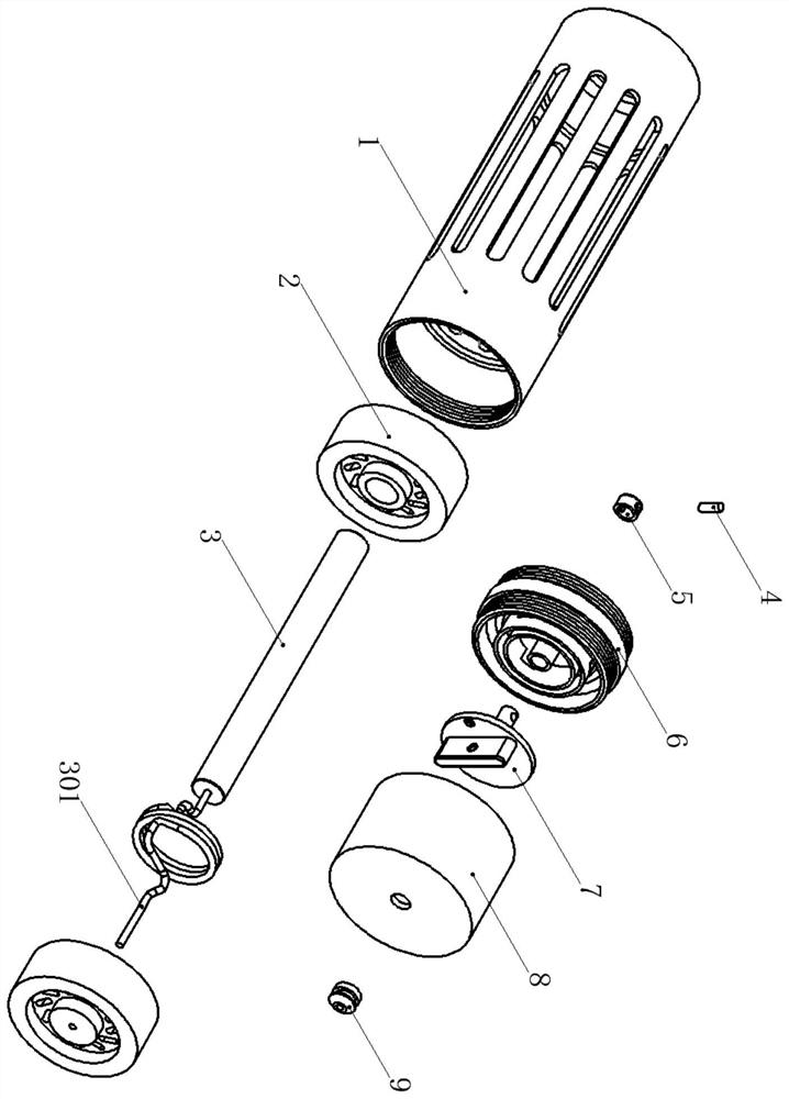
[0029] refer to Figure 1-Figure 3 A thermocouple connection structure with impact protection function, including a protective shell 1, a shock absorbing support ring 2, a thermocouple 3, a connecting pin 4, a sleeve 5, a middle connector 6, a winding cover 7, a tail cover 8 and line pad 9, the shock-absorbing support ring 2 is provided with two and sleeved at both ends of the thermocouple 3, the thermocouple 3 and the two shock-absorbing support rings 2 are l...


PUM


Abstract

The invention discloses a thermocouple connecting structure with an impact protection function, which comprises a protective shell, two damping bearing rings, a thermocouple, a connecting pin, a sleeve, a middle connecting piece, a rolling cover, a tail cover and a wire pad. The two damping bearing rings sleeve the two ends of the thermocouple, and the thermocouple and the two damping bearing rings are located in the protective shell; the middle connecting piece is in threaded connection with the sleeve, the winding cover is installed in the middle connecting piece through the connecting pin and the sleeve, the tail cover is in threaded connection with the middle connecting piece, the wire pad is located in the tail cover, a data line of the thermocouple penetrates through the middle connecting piece, the winding cover, the tail cover and the wire pad, and the contour of the protective shell is in a circular tube shape. Shell grooves distributed in an annular array mode are formed in the outer circle face of the protective shell. The thermocouple connection structure with the impact protection function can well protect the thermocouple, can also tidily collect the data line of the thermocouple, and is suitable for general popularization and application.

Description

technical field [0001] The invention belongs to the technical field of thermocouples, and in particular relates to a thermocouple connection structure with impact protection function. Background technique [0002] Thermocouple is a commonly used temperature measuring element in temperature measuring instruments. It directly measures the temperature, and converts the temperature signal into a thermal electromotive force signal, and converts it into the temperature of the measured medium through an electrical instrument. The shapes of various thermocouples are often very different due to needs, but their basic structures are roughly the same, usually composed of main parts such as thermal electrodes, insulating sleeve protection tubes, and junction boxes, and are usually associated with display instruments, recording instruments, and electronic regulators. used together with the device. [0003] Thermocouples are sometimes installed in vibration containers. Existing thermocou...

Claims


Application Information

Patent Timeline
Patent Type & Authority Applications(China)
IPC IPC(8): G01K1/14G01K1/08G01K7/02
CPCG01K1/14G01K1/08G01K7/02Y02E30/30
Inventor 张洋
Owner 安徽福特控制系统有限公司
Learn More