Flow regulating valve and supermagnetic separation equipment using the flow regulating valve
A flow control valve and valve body technology, which is applied in mechanical equipment, water/sewage treatment equipment, valve operation/release devices, etc., can solve the problems of high cost and complicated structure of electric flow control valves, and achieve low cost and good structure simple effect
- Summary
- Abstract
- Description
- Claims
- Application Information
AI Technical Summary
Problems solved by technology
Method used
Image
Examples
Embodiment 1
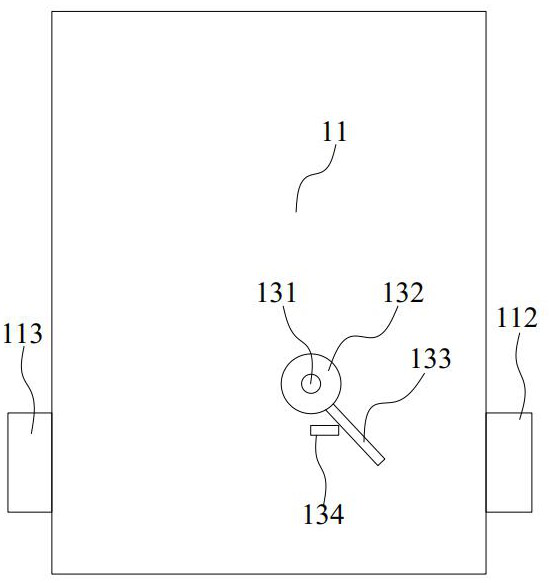
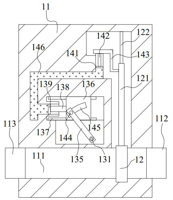
[0080] Please refer to Figure 1-Figure 5 , the present embodiment provides a regulating valve, which may mainly include: a valve body 11, a valve plate 12, a driving mechanism and an anti-clogging mechanism. The driving mechanism is used to drive the valve plate 12 to move up or down, and the anti-clogging mechanism is used to prevent the regulating valve from being blocked by sundries.
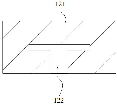
[0081] A flow passage 111 is opened in the valve body 11 , and two ends of the flow passage 111 are respectively connected with a water inlet head 112 and a water outlet head 113 . The valve plate 12 is movably arranged in the valve body 11 , and the valve plate 12 can block the flow channel 111 . The valve plate 12 is made of metal material, and the top of the valve plate 12 is connected with a lifting plate 121 , and the lifting plate 121 is slidably connected with a guide rail 122 , and the guide rail 122 is longitudinally installed in the valve body 11 .
[0082] The driving mechanism ...
Embodiment 2
[0088]This embodiment is a further improvement made on the basis of Embodiment 1.
[0089] Please refer to Figure 1-Figure 6 , in this embodiment, the third bevel gear is installed on the first support rod 151, the lower end of the first support rod 151 is provided with a connecting column 252, and the lower end of the connecting column 252 is connected to the second support rod 253 through bearing rotation, the second A plurality of second cleaning teeth 254 are arranged on the second support rod 253 , and the lower end of the second support rod 253 is rotatably connected to the valve body.
[0090] Through the setting of the connecting column 252, the second support rod 253 and the second cleaning teeth 254, when the first support rod 151 is not rotating, the second support rod 253 can rotate under the drive of the water flow to stir the water inlet head and The sundries between the valve plates can prevent the regulating valve from being blocked.
Embodiment 3
[0092] This embodiment is another implementation of the driving assembly provided by the present invention.
[0093] Please refer to Figure 1-Figure 11 , in this embodiment, the driving assembly may further include a driving rod 352 , a first connecting pipe 353 and a second connecting pipe 354 . The third bevel gear is installed on the top of the drive rod 352, the bottom of the drive rod 352 is fixed with a cylinder 355, and one side of the drive rod 352 is provided with a first transfer block 356 and a second transfer block 357, the first transfer block 356 is rotatably connected with a first transfer shaft 358 , a first torsion spring (not shown in the figure) is arranged on the first transfer shaft 358 , and a first drive tooth 359 is connected to the first transfer shaft 358 . A second transfer shaft 361 is rotatably connected to the second transfer block 357, a second torsion spring (not shown in the figure) is arranged on the second transfer shaft 361, and a second d...
PUM
 Abstract
Description
Claims
Application Information
 - R&D
- Intellectual Property
- Life Sciences
- Materials
- Tech Scout
- Unparalleled Data Quality
- Higher Quality Content
- 60% Fewer Hallucinations
Browse by: Latest US Patents, China's latest patents, Technical Efficacy Thesaurus, Application Domain, Technology Topic, Popular Technical Reports.
© 2025 PatSnap. All rights reserved.Legal|Privacy policy|Modern Slavery Act Transparency Statement|Sitemap|About US| Contact US: help@patsnap.com


