
Circuit board testing device

A test device, circuit board technology, applied in the direction of electronic circuit test, printed circuit test, measuring device, etc., can solve problems such as unsuitable connection test, large size, etc.

Pending Publication Date: 2021-08-20
GREE ELECTRIC APPLIANCES WUHAN +1
View PDF0 Cites 0 Cited by
  • Summary
  • Abstract
  • Description
  • Claims
  • Application Information

AI Technical Summary

Problems solved by technology

[0002] At present, the size of the circuit board testing device in the related art is relatively large, and when the specification of the circuit board to be tested is small, it is not suitable for connection testing.

Method used


Image

  • Circuit board testing device
  • Circuit board testing device

Examples


Embodiment Construction

[0025] The present invention will be further described below in conjunction with accompanying drawing.

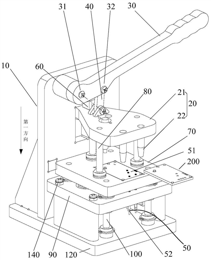
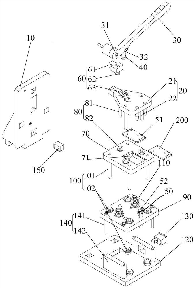
[0026] It should be noted that the circuit board test device in this application is mainly used for the test of circuit boards with small specifications. The test device has high stability and is composed of simple parts. diversity requirements. The circuit board test device in this application replaces the test method of manual point-to-point docking in the related art, thereby avoiding the problems of poor contact and inaccurate testing caused by this test method.

[0027] It should be noted that the first direction in this application refers to figure 1 in the vertical direction. The pressing mechanism in this application is a rocker slider mechanism, and the dead point position of the rocker slider mechanism is the pressing position where the top plate 20 presses the circuit board 200 to be tested. Dead point position is meant that connecting rod 40 rotates to its ax...


PUM


Abstract

The present invention provides a circuit board testing device. The device comprises: a branch pressing mechanism comprising a top tray; and a bearing assembly electrically connected with an external test instrument. The pressing mechanism is provided with a dead point position, and when the pressing mechanism is located at the dead point position, the to-be-tested circuit board is pressed and contacted on the bearing assembly by the top plate, so that the to-be-tested circuit board is conducted with an external testing instrument. Based on the technical scheme, the circuit board testing device does not need to be additionally provided with a locking mechanism to achieve the locking function o fa top plate at the pressing position, so that the structure of the circuit board testing device is greatly simplified, and a rocker sliding block mechanism is simple in structure. Therefore, when the pressing mechanism adopts the rocker sliding block mechanism, the overall size of the circuit board testing device can be reduced, so that the circuit board testing device is suitable for testing circuit boards with small specifications.

Description

technical field [0001] The invention relates to the technical field of circuit board testing, in particular to a circuit board testing device. Background technique [0002] At present, the size of the circuit board testing device in the related art is relatively large, and when the specification of the circuit board to be tested is small, it is not suitable for connection testing. [0003] That is to say, there is an urgent need to develop a test device suitable for circuit boards with smaller specifications. Contents of the invention [0004] Aiming at the above-mentioned problems in the prior art, the present application proposes a circuit board testing device, which is suitable for testing circuit boards with smaller specifications. [0005] The circuit board testing device of the present invention includes: a pressing mechanism, including a sky plate; a bearing assembly, electrically connected to an external testing instrument; wherein, the pressing mechanism has a de...

Claims


Application Information

Patent Timeline
IPC IPC(8): G01R31/28G01R1/04
CPCG01R1/0408G01R31/2808
Inventor 徐军翟志强汪开烽雷静美王中兴
Owner GREE ELECTRIC APPLIANCES WUHAN
Learn More