
Single-stage porous throttling orifice plate and throttling device

A technology of throttling orifice plate and orifice, which is applied in the direction of pipe components, mechanical equipment, pipes/pipe joints/pipe fittings, etc., can solve problems such as loud noise and pipe vibration, reduce noise, improve flow field, and ensure sealing performance effect

Pending Publication Date: 2021-08-20
SHANDONG ELECTRIC POWER ENG CONSULTING INST CORP
View PDF10 Cites 2 Cited by
  • Summary
  • Abstract
  • Description
  • Claims
  • Application Information

AI Technical Summary

Problems solved by technology

[0004] The throttling orifice is mainly used to decompress the medium in the pipeline. When designing only a single-hole orifice, the inventor found that when the flow aperture of the throttling orifice is selected to be small, the flow area of ​​the throttling orifice will be larger than the design. When the system is put into operation, the flow field of the medium before and after the throttle orifice is likely to change drastically, resulting in loud noise and vibration problems in the pipeline
[0005] In addition, the site often encounters the need to adjust the flow area of ​​the throttle orifice. When procurement is difficult, it is necessary to process and manufacture a new throttle orifice on site. Although the throttle orifice made on site is more throttle than the finished product The orifice plate can also play a throttling effect, but the inventor found that the throttling aperture of the throttling orifice plate made on site may not be able to adapt to the throttling effect

Method used


Image

  • Single-stage porous throttling orifice plate and throttling device
  • Single-stage porous throttling orifice plate and throttling device
  • Single-stage porous throttling orifice plate and throttling device

Examples


Embodiment 1

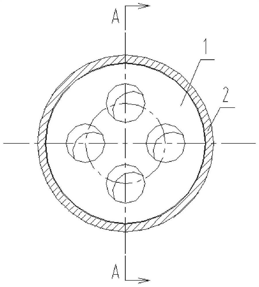
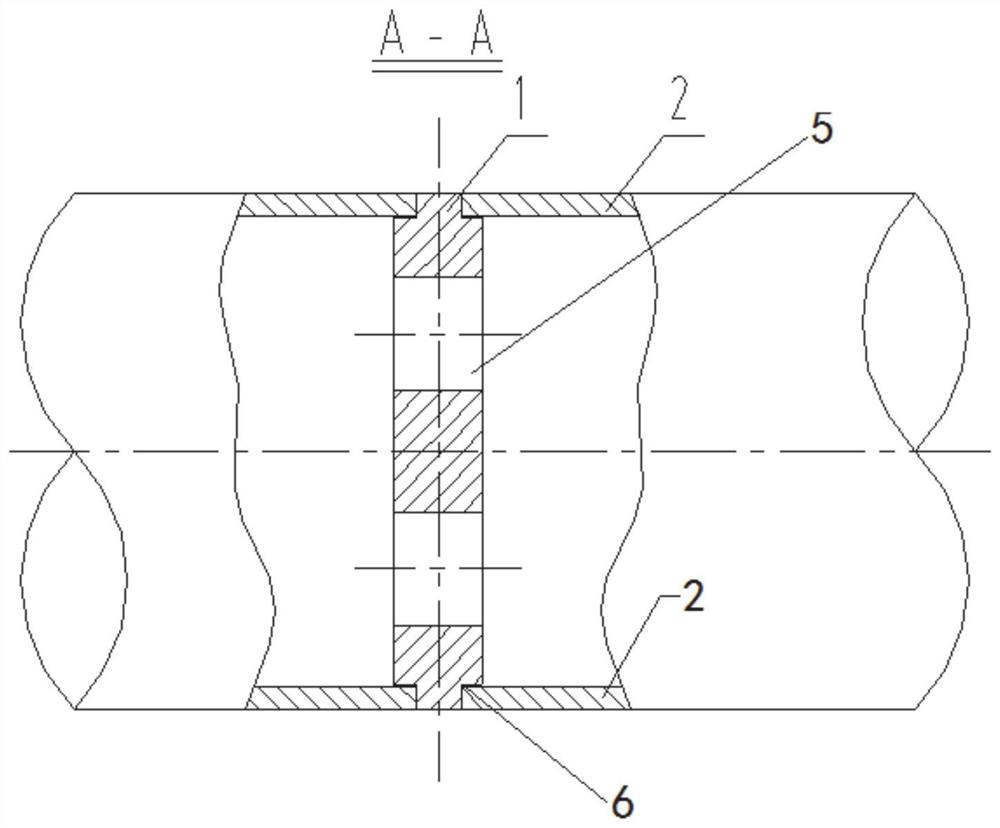
[0058] In a typical embodiment of the present invention, a single-stage multi-hole throttle orifice plate includes a plate body 1, the plate body 1 has a set thickness and the size of the plate body is adapted to the size of the pipeline 2, and the plate body 1 is opened There are at least two throttling holes 5, and a plurality of throttling holes 5 are arranged around the center axis of the plate body 1, or one of the throttling holes is arranged at the center of the plate body.

[0059] The above-mentioned single-stage multi-hole throttling orifice can be divided into two types: welding connection and flange clamping connection.

[0060] In this embodiment, for the throttling orifice plate connected by welding, in order to further ensure the cooperation between the plate body and the pipeline, refer to figure 1 with figure 2 As shown, the two ends of the board are provided with steps 6 in the circumferential direction, so that groove structures are formed on both ends of...

Embodiment 2

[0077] The difference between this embodiment and the first embodiment is that the throttle orifice is connected by flange clamping.

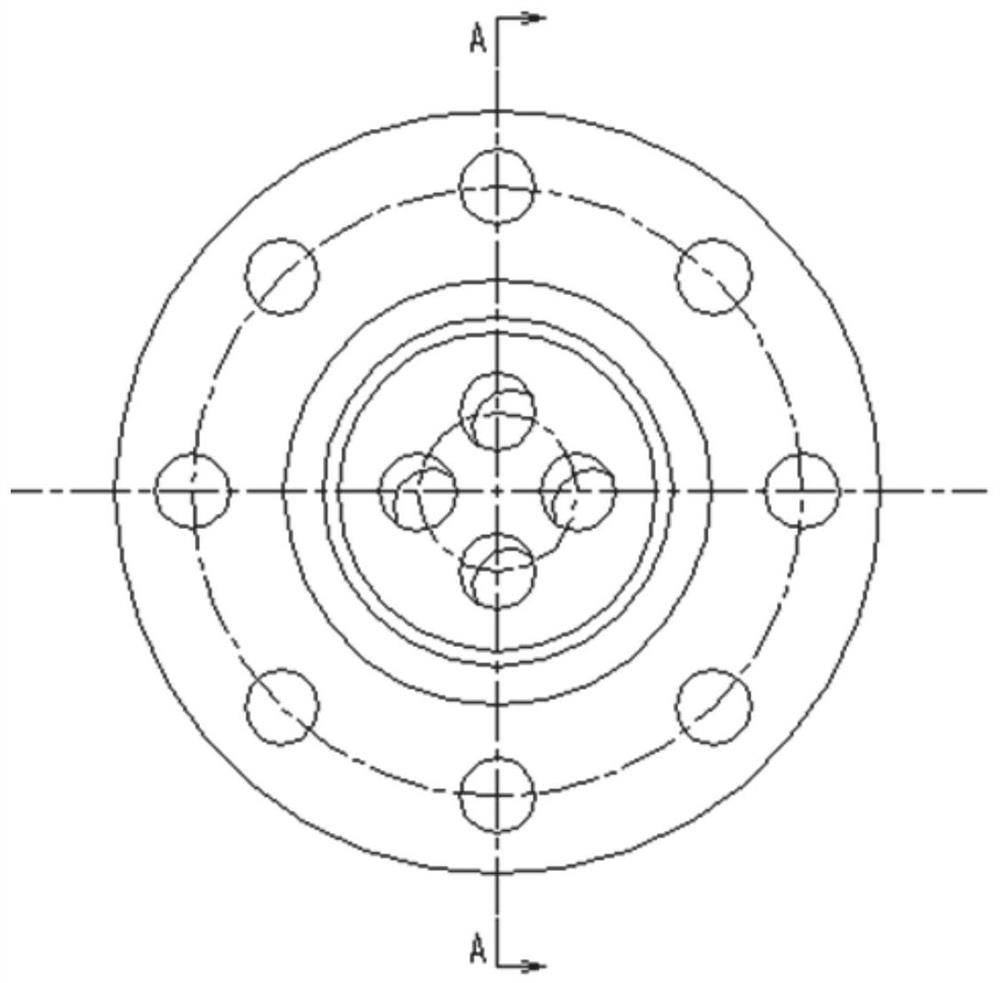
[0078] For flange clamp orifice installations, refer to image 3 with Figure 4 As shown, the diameter of the flange is larger than the diameter of the plate body, and the ends of the pipes are connected by flanges. A throttling orifice plate with a set thickness is arranged between the two flanges, and the diameter of the plate body is larger than that of the connecting flange with the same plate body That is the inner diameter of the pipe.

[0079] For the flange clamping connection method, the diameter of the plate body is larger than the inner diameter of the flange and correspondingly larger than the inner diameter of the pipe connected to the flange.

Embodiment 3

[0081] This embodiment provides a throttling device, including the single-stage multi-hole throttling orifice described in Embodiment 1 or Embodiment 2.

[0082] In some examples, a throttling device further includes flanges, the flanges can be connected to the pipeline, and the distance between the two flanges is set to prevent the flange contact from affecting the throttling effect of the throttling plate. (Adjacent side between two adjacent flanges) set a groove that can accommodate part of the throttle orifice, and accommodate the throttle orifice through the grooves of two adjacent flanges, so that the throttle orifice can be set in the groove The fit of the flange improves the reliability of the connection between the flange and the board.

[0083] The diameter of the groove is larger than the inner diameter of the pipe. Correspondingly, the size of the plate body is larger than the inner diameter of the pipe. Considering the convenience of the installation of the thrott...


PUM


Abstract

The invention discloses a single-stage porous throttling orifice plate and a throttling device and solves the problems of loud noise and pipeline vibration of the throttling orifice plate in the prior art. The beneficial effects of reducing pipeline noise and vibration and conveniently manufacturing on site can be achieved. The specific scheme is as follows: the single-stage porous throttling orifice plate comprises a plate body, wherein the plate body has set thickness; the size of the plate body is matched with the size of a pipeline; the plate body is provided with at least two throttling holes; a plurality of throttling holes are annularly distributed by taking the central axis of the plate body as the center; or one of the plurality of throttling holes is formed in the center of the plate body.

Description

technical field [0001] The invention relates to the field of thermal power plants, in particular to a single-stage multi-hole throttling orifice plate and a throttling device. Background technique [0002] The statements in this section merely provide background information related to the present invention and do not necessarily constitute prior art. [0003] Throttle orifice plates are often used as decompression components in steam and water pipelines in thermal power plants. In the typical design manual for steam and water pipeline parts and components in thermal power plants, it can be found that the finished orifice plates have multi-stage orifice plates and single-stage orifice plates. Orifice plate: In the actual design of steam-water pipelines in thermal power plants, a single-stage throttle orifice can be made on site, that is, a round hole is drilled in the center of the steel plate to be used as a single-stage throttle orifice. The above several throttling orific...

Claims


Application Information

Patent Timeline
Patent Type & Authority Applications(China)
IPC IPC(8): F16L55/027
CPCF16L55/02718
Inventor 祁金胜苗井泉姬锋军张涛田林李琳马强李传永隋菲菲王刚
Owner SHANDONG ELECTRIC POWER ENG CONSULTING INST CORP
Learn More